


Dahua Network Video Server
User’s Manual
104
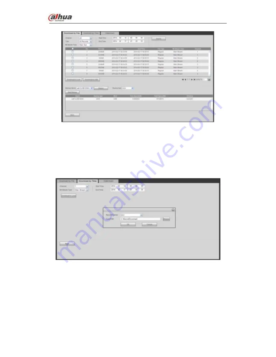
Figure 4-132
Select Backup device and backup type first and then click Start backup button.
After the download operation, you can see corresponding dialogue box.
4.5.6.2 Download by Time
Select channel, bit stream type, start time and end time.
Click Download to Local button, you can see download by time interface is shown as in
Figure 4-133.
Figure 4-133
Set record format and saved path, you can click OK to download and view the download
process. After the download operation, you can see corresponding dialog box.
4.5.6.3 Watermark
Watermark interface is shown as In Figure 4-134. Please select a file and then click Verify
button to see the file has been tampered with or not


