413
Please refer to the following sheet for detailed information.
Parameter
Function
Enable tour
Check the box here to enable tour function.
Interval
Here is for you to adjust transparency. The value ranges from 5 to
120s. The default setup is 5s.
Split
Here you can set window mode and channel group. System can
support 1/4/8/9/16/25/36-window according to device channel
amount.
Motion
tour/Alarm
tour
Here you can set motion detect tour/alarm tour window mode.
System supports 1/8-window now.
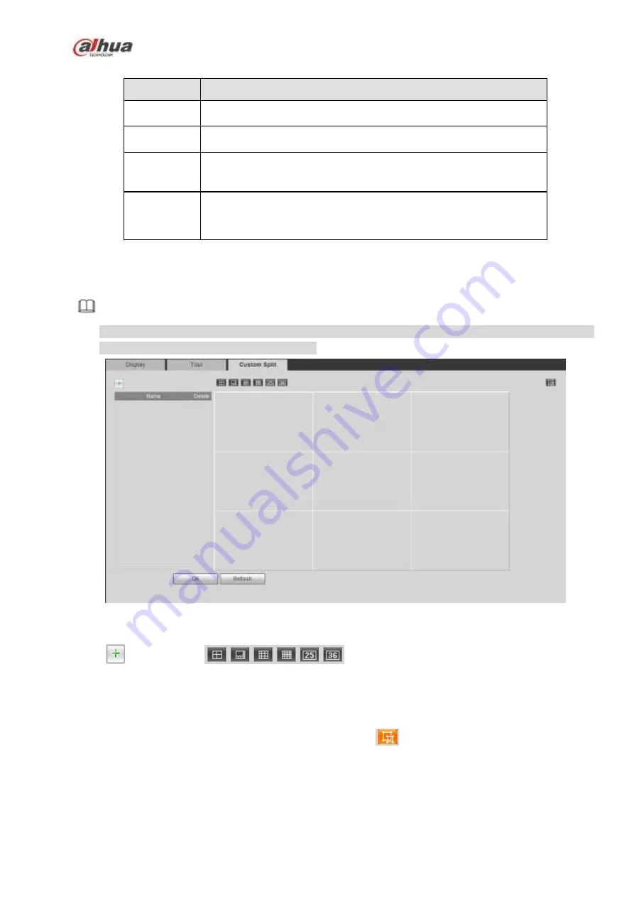
5.10.5.2.1 Custom Split
From main menu->Setup->System->Display->Custom split, the interface is shown as in Figure 5-118.
Here you can set customized split mode.
Note
This function is for some series products. Please refer to the actual product for detailed information.
Device max supports 5 customized videos.
Figure 5-118
Click
and then click
to select basic mode
In regular mode, drag the mouse in the preview frame, you can merge several small windows to one
window so that you can get you desired split mode.
After the setup, the selected window has the red frame.
Select the merging window, the frame is red; you can click
to cancel the merge to restore regular
mode.
Click OK to exit.
5.10.5.3 RS232
The RS232 interface is shown as in Figure 5-119.
Содержание NVR21-S2 SERIES
Страница 1: ...Dahua Network Video Recorder User s Manual V 4 3 0...
Страница 138: ...124 Figure 3 5 3 6 6 NVR42N Series Please refer to Figure 3 6 for connection sample Figure 3 6...
Страница 142: ...128 Figure 3 11 3 6 12 NVR42V 8P Series Please refer to Figure 3 12 for connection sample...
Страница 143: ...129 Figure 3 12...
Страница 157: ...143 Figure 4 15 Step 2 Click device display edit interface See Figure 4 16...
Страница 220: ...206 Figure 4 93 Figure 4 94...
Страница 240: ...226 Figure 4 110 Figure 4 111 Figure 4 112...
Страница 251: ...237 Figure 4 123 Figure 4 124...
Страница 253: ...239 Figure 4 126 Click draw button to draw the zone See Figure 4 127...
Страница 257: ...243 Figure 4 130 Click Draw button to draw a zone See Figure 4 131 Figure 4 131...
Страница 262: ...248 Figure 4 136 Click draw button to draw the zone See Figure 4 137...
Страница 275: ...261 Figure 4 148 Figure 4 149...
Страница 276: ...262 Figure 4 150 Figure 4 151...
Страница 387: ...373 Figure 5 60 Figure 5 61...
Страница 388: ...374 Figure 5 62 Figure 5 63...
Страница 412: ...398 Figure 5 96 Figure 5 97...
Страница 418: ...404 Figure 5 106 5 10 4 4 Record Control The interface is shown as in Figure 5 107 Figure 5 107...


