198
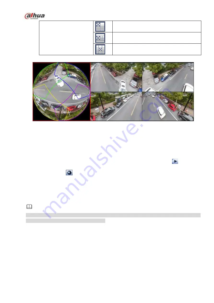
1 panorama unfolding view+3 de-warp windows
1 panorama unfolding view +4 de warp windows
1 panorama unfolding view +8 de warp windows
Figure 4-80
In Figure 4-80, you can adjust the color pane on the left pane or use your mouse to change the
position of the small images on the right pane to realize fish eye de-warp.
4.3.7.2 Fish eye de-warp during playback
Step 1 On the main menu, click search button.
Step 2 Select 1-window playback mode and corresponding fish eye channel, click
to play.
Step 3 Right click the
, you can go to the de-warp playback interface. For detailed information,
please refer to chapter 4.3.7.1 fisheye de-warp during preview.
4.4 PTZ
Note
Before you control the PTZ, please make sure the PTZ decoder and the NVR network connection is
OK and the corresponding settings are right.
4.4.1
PTZ Settings
Cable Connection
Please follow the procedures below to go on cable connection
Connect the dome RS485 port to NVR RS485 port.
Connect dome video output cable to NVR video input port.
Connect power adapter to the dome.
In the main menu, from Setting->System->PTZ, you can see an interface is shown as in Figure 4-81.
Here you can set the following items:
Channel: Select the current camera channel.
Содержание NVR21-S2 SERIES
Страница 1: ...Dahua Network Video Recorder User s Manual V 4 3 0...
Страница 138: ...124 Figure 3 5 3 6 6 NVR42N Series Please refer to Figure 3 6 for connection sample Figure 3 6...
Страница 142: ...128 Figure 3 11 3 6 12 NVR42V 8P Series Please refer to Figure 3 12 for connection sample...
Страница 143: ...129 Figure 3 12...
Страница 157: ...143 Figure 4 15 Step 2 Click device display edit interface See Figure 4 16...
Страница 220: ...206 Figure 4 93 Figure 4 94...
Страница 240: ...226 Figure 4 110 Figure 4 111 Figure 4 112...
Страница 251: ...237 Figure 4 123 Figure 4 124...
Страница 253: ...239 Figure 4 126 Click draw button to draw the zone See Figure 4 127...
Страница 257: ...243 Figure 4 130 Click Draw button to draw a zone See Figure 4 131 Figure 4 131...
Страница 262: ...248 Figure 4 136 Click draw button to draw the zone See Figure 4 137...
Страница 275: ...261 Figure 4 148 Figure 4 149...
Страница 276: ...262 Figure 4 150 Figure 4 151...
Страница 387: ...373 Figure 5 60 Figure 5 61...
Страница 388: ...374 Figure 5 62 Figure 5 63...
Страница 412: ...398 Figure 5 96 Figure 5 97...
Страница 418: ...404 Figure 5 106 5 10 4 4 Record Control The interface is shown as in Figure 5 107 Figure 5 107...


