
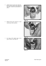
S0709730K
Page 5
Power Steering Unit
Return to Master Table of Contents
Neutral Operation
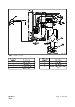
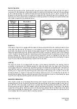
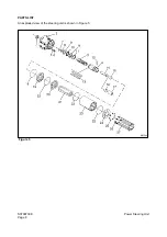
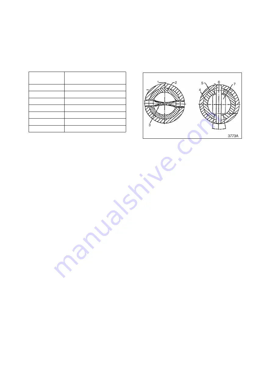
With the steering wheel in the neutral position (wheels turned neither right nor left), the spool (2, Figure 3)
and sleeve (1) are stationary at the position where the center pin (6) becomes centered in the spool space
by the centering springs (3). Oil flow through the load sensing line (LS), port L, port R, and port T are
bypassed to the tank line and the oil supply (P) is blocked by the directional spool in the steering unit (1,
Figure 2). Even if an external force is applied to the steering cylinder, the steering unit is protected because
the oil path is blocked by the directional spool.
Right Turn
The spool (2, Figure 3) is engaged with the spline of the steering shaft. When the steering wheel is turned
to the right, the spool turns. The sleeve (1) is connected to the spool (2) by centering springs (3). When
spool turns, the sleeve turns. The sleeve turning angle is about 10° less than the spool turning angle. This
allows the longitudinal slots in the spool to align with the ports in the sleeve. Oil from port P on the steering
unit (1, Figure 2) travels through the control spool and is directed to port R which directs the oil to the
steering cylinders (3, Figure 2). The amount of flow metered to port R is controlled by the amount of
steering wheel rotation. Excess oil flow through port P that is not metered to port R, is directed by the spool
to port T and is then directed through the il cooler and into the tank.
Left Turn
The spool (2, Figure 3) is engaged with the spline of the steering shaft. When the steering wheel is
connected to the spool (2) by centering springs (3). When the spool turns, the sleeve turns. The sleeve
turning angle is about 10° less than the spool turning angle. This allows the longitudinal slots in the spool to
align with the ports in the sleeve. When the steering wheel is turned to the left, oil from port P on the
steering unit (1, Figure 2) is directed through the control spool in the steering unit, out port L and into the
steering cylinders (3, Figure 2). The amount of oil flow metered to port L is controlled by the amount of
steering wheel rotation. Excess oil flow through port P that is not metered to port L, is directed by the spool
to port T and is then directed through the oil cooler and into the tank.
GEROTOR OPERATION
If the engine or pump is not operating, the steering unit (1, Figure 2) works as a manual pump when the
steering wheel is turned. The gerotor will work when the input torque to the steering wheel is less than 12
kg•m (87 ft lb). If the necessary input torque is greater than this, the gerotor will not function. When the
steering wheel is turned, the gerotor creates a vacuum that draws oil from port T. See Figure 2. The gerotor
pumps this oil through the control spool and into the steering cylinders. Return oil flows back to the spool
and is used to lubricate the steering unit (1, Figure 2). The return oil then flows back into the tank line and
is recirculated back to the gerotor and the steering cylinders.
Reference
Number
Description
1
Sleeve
2
Spool
3
Centering Spring
4
Spool
5
Sleeve
6
Center Pin
7
Drive shaft
Figure 3
Содержание Mega 500-V
Страница 4: ...1SAFETY ...
Страница 41: ...1SPECIFICATIONS ...
Страница 47: ...S0203070K Page 6 Specifications for Mega 500 V ENGINE PERFORMANCE CURVES AHS3720L Figure 2 ...
Страница 55: ...S0203070K Page 14 Specifications for Mega 500 V ...
Страница 56: ...1GENERAL MAINTENANCE ...
Страница 70: ...S0302000 Page 14 General Maintenance Procedures Return to Master Table of Contents ...
Страница 83: ...1UPPER STRUCTURE ...
Страница 85: ...S0403040K Page 2 Counterweight TABLE OF CONTENTS Specifications 3 Counterweight 3 ...
Страница 87: ...S0403040K Page 4 Counterweight ...
Страница 95: ...S0406040K Page 2 Hydraulic Oil Tank TABLE OF CONTENTS General Description 3 Parts List 3 Specifications 4 ...
Страница 98: ...1LOWER STRUCTURE AND CHASSIS ...
Страница 100: ...S0502020K Page 2 Center Joint Articulation Joint TABLE OF CONTENTS General Description 3 Maintenance Standard 4 ...
Страница 104: ...S0502020K Page 6 Center Joint Articulation Joint ...
Страница 105: ...1ENGINE AND DRIVE TRAIN ...
Страница 117: ...S0602170K Page 12 Axle ZF AP 420R Pinion distance must be decreased Figure 5 Figure 6 Figure 7 Figure 8 ...
Страница 118: ...S0602170K Page 13 Axle ZF AP 420R Figure 9 ...
Страница 119: ...S0602170K Page 14 Axle ZF AP 420R ...
Страница 121: ...S0602170K Page 16 Axle ZF AP 420R FINAL DRIVE AP 407 409 Figure 10 ...
Страница 123: ...S0602170K Page 18 Axle ZF AP 420R AP 411 415 Figure 11 ...
Страница 125: ...S0602170K Page 20 Axle ZF AP 420R AP 417 420 Figure 12 ...
Страница 127: ...S0602170K Page 22 Axle ZF AP 420R DIFFERENTIAL VERSION SCREWED BEARING CAPS Differential Carrier CK Figure 13 ...
Страница 129: ...S0602170K Page 24 Axle ZF AP 420R Differential Carrier RK Figure 14 ...
Страница 131: ...S0602170K Page 26 Axle ZF AP 420R Differential Carrier DK ...
Страница 133: ...S0602170K Page 28 Axle ZF AP 420R DIFFERENTIAL VERSION CAST ON BEARING CAPS Differential Carrier DK Figure 15 ...
Страница 135: ...S0602170K Page 30 Axle ZF AP 420R Differential Carrier HK Figure 16 ...
Страница 178: ...S0602170K Page 73 Axle ZF AP 420R ILLUSTRATED TABLE Figure 152 ...
Страница 194: ...S0602170K Page 89 Axle ZF AP 420R ILLUSTRATED TABLE Figure 196 ...
Страница 210: ...S0602170K Page 105 Axle ZF AP 420R ILLUSTRATED TABLE Figure 242 ...
Страница 225: ...S0602170K Page 120 Axle ZF AP 420R ILLUSTRATED TABLE Figure 289 ...
Страница 251: ...S0605050K Page 26 Air Conditioner Return to Master Table of Contents ...
Страница 261: ...S0607080K Page 10 Transmission and Torque Converter ZF 4WG 310 Figure 2 ...
Страница 264: ...S0607080K Page 13 Transmission and Torque Converter ZF 4WG 310 ...
Страница 271: ...S0607080K Page 20 Transmission and Torque Converter ZF 4WG 310 ...
Страница 291: ...S0607080K Page 40 Transmission and Torque Converter ZF 4WG 310 INSTALLATION VIEW INNER SECTION Figure 36 ...
Страница 296: ...S0607080K Page 45 Transmission and Torque Converter ZF 4WG 310 ...
Страница 447: ...S0607900C Page 36 Transmission Error Codes ZF ...
Страница 448: ...1HYDRAULICS ...
Страница 478: ...S0705010 Page 22 Cylinders Return to Master Table of Contents ...
Страница 489: ...S0708460K Page 11 Main Pump Denison T6DMY Series ...
Страница 490: ...S0708460K Page 12 Main Pump Denison T6DMY Series PARTS LIST Figure 8 ...
Страница 504: ...S0708460K Page 26 Main Pump Denison T6DMY Series ...
Страница 508: ...S0708470K Page 4 Steering and Brake Pump Denison T67DB Series PARTS LIST Figure 2 ...
Страница 514: ...S0708470K Page 10 Steering and Brake Pump Denison T67DB Series DISASSEMBLY Figure 5 ...
Страница 521: ...S0708470K Page 17 Steering and Brake Pump Denison T67DB Series ...
Страница 522: ...S0708470K Page 18 Steering and Brake Pump Denison T67DB Series REASSEMBLY Figure 15 ...
Страница 528: ...S0708470K Page 24 Steering and Brake Pump Denison T67DB Series ...
Страница 548: ...S0709476K Page 2 Pilot Control Valve Return to Master Table of Contents ...
Страница 554: ...S0709476K Page 8 Pilot Control Valve Return to Master Table of Contents ...
Страница 557: ...S0709665K Page 3 Flow Amplifier Danfoss GENERAL DESCRIPTION Figure 1 ...
Страница 558: ...S0709665K Page 4 Flow Amplifier Danfoss PARTS LIST Figure 2 ...
Страница 561: ...S0709665K Page 7 Flow Amplifier Danfoss TROUBLESHOOTING TESTING AND ADJUSTMENT Figure 4 Flow Amplifier Circuit ...
Страница 582: ...S0709665K Page 28 Flow Amplifier Danfoss H Shock valve suction valve shown dismantled Figure 63 ...
Страница 609: ...S0709730K Page 7 Power Steering Unit Return to Master Table of Contents ...
Страница 632: ...S0709730K Page 30 Power Steering Unit Return to Master Table of Contents ...
Страница 638: ...S0709750K Page 6 Restriction Valve Return to Master Table of Contents ...
Страница 642: ...S0793060K Page 4 Hydraulic Schematic Mega 500 V Return to Master Table of Contents MEGA 500 V Figure 2 ...
Страница 644: ...S0793060K Page 6 Hydraulic Schematic Mega 500 V Return to Master Table of Contents ...
Страница 645: ...1ELECTRICAL SYSTEM ...
Страница 654: ...S0802190K Page 9 Electrical System Return to Master Table of Contents ...
Страница 658: ...S0802190K Page 13 Electrical System Return to Master Table of Contents ...
Страница 676: ...S0802190K Page 31 Electrical System Return to Master Table of Contents ...
Страница 683: ...S0893060K Page 4 Electrical Schematic Mega 500 V Return to Master Table of Contents MEGA 500 V Figure 2 ...
Страница 684: ...S0893060K Page 5 Electrical Schematic Mega 500 V Return to Master Table of Contents AHS3680L MEGA 500 V ...
Страница 685: ...S0893060K Page 6 Electrical Schematic Mega 500 V Return to Master Table of Contents ...
Страница 686: ...1ATTACHMENTS ...