


S0607900C
Page 28
Transmission Error Codes (ZF)
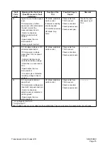
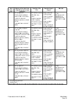
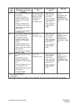
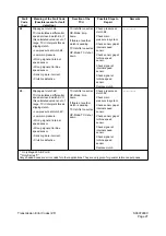
B6
Slippage at clutch KR.
TCU calculates a differential
speed at closed clutch KR. If
this calculated value is out of
range, TCU interprets this as
slipping clutch.
• Low pressure at clutch KR.
• Low main pressure.
• Wrong signal at internal
speed sensor.
• Wrong signal at turbine
speed sensor.
• Sensor gap is incorrect.
• Clutch is defective.
TCU shifts to neutral.
OP-Mode: limp
home.
If failure at another
clutch is pending.
TCU shifts to neutral.
OP-Mode: TCU shut
down.
Check pressure at
clutch KR.
Check main
pressure in system.
Check sensor gap at
internal speed
sensor.
Check sensor gap at
turbine speed
sensor.
Check signal at
internal speed
sensor.
Check signal at
turbine speed
sensor.
Replace clutch.
---------------
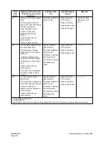
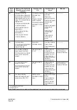
B7
Overtemp sump.
TCU measured a temperature
in oil sump that is over
allowed threshold.
No reaction.
OP-Mode: normal.
Cool down machine.
Check oil level.
Check temperature
sensor.
---------------
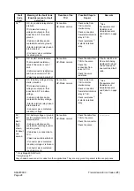
D1
S.C. to battery voltage at
power supply for sensors.
TCU measures more than 6V
at the pin AU1 (5V sensor
supply).
See fault codes No.
21 - 2C.
Check cables and
connectors to
sensors, which are
supplied from AU1.
Check the power
supply at the pin AU1
(should be
approximately 5V).
Fault codes No. 21 to
No. 2C may be a
reaction of this fault.
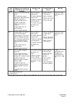
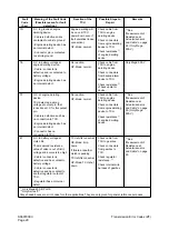
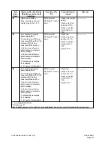
D2
S.C. to ground at power
supply for sensors.
TCU measures less than 4V
at the pin AU1 (5V sensor
supply).
See fault codes No.
21 - 2C.
Check cables and
connectors to
sensors, which are
supplied from AU1.
Check the power
supply at the pin AU1
(should be
approximately 5V).
Fault codes No. 21 to
No. 2C may be a
reaction of this fault.
D3
Low power at battery.
Measured voltage at power
supply is lower than 18 V.
Shift to neutral.
OP-Mode: TCU shut
down.
Check power supply
battery.
Check cables from
batteries to TCU.
Check connectors
from batteries to
TCU.
---------------
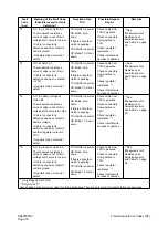
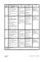
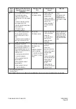
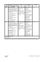
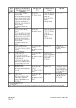
Fault
Code
(hex)
Meaning of the Fault Code
(Possible reason for fault
detection.)
Reaction of the
TCU
Possible Steps to
Repair
Remarks
* Only Mega 400-III PLUS
** Only Series "V"
Gray shaded boxes are error codes for other applications. They are only given for general reference purposes.
Содержание Mega 500-V
Страница 4: ...1SAFETY ...
Страница 41: ...1SPECIFICATIONS ...
Страница 47: ...S0203070K Page 6 Specifications for Mega 500 V ENGINE PERFORMANCE CURVES AHS3720L Figure 2 ...
Страница 55: ...S0203070K Page 14 Specifications for Mega 500 V ...
Страница 56: ...1GENERAL MAINTENANCE ...
Страница 70: ...S0302000 Page 14 General Maintenance Procedures Return to Master Table of Contents ...
Страница 83: ...1UPPER STRUCTURE ...
Страница 85: ...S0403040K Page 2 Counterweight TABLE OF CONTENTS Specifications 3 Counterweight 3 ...
Страница 87: ...S0403040K Page 4 Counterweight ...
Страница 95: ...S0406040K Page 2 Hydraulic Oil Tank TABLE OF CONTENTS General Description 3 Parts List 3 Specifications 4 ...
Страница 98: ...1LOWER STRUCTURE AND CHASSIS ...
Страница 100: ...S0502020K Page 2 Center Joint Articulation Joint TABLE OF CONTENTS General Description 3 Maintenance Standard 4 ...
Страница 104: ...S0502020K Page 6 Center Joint Articulation Joint ...
Страница 105: ...1ENGINE AND DRIVE TRAIN ...
Страница 117: ...S0602170K Page 12 Axle ZF AP 420R Pinion distance must be decreased Figure 5 Figure 6 Figure 7 Figure 8 ...
Страница 118: ...S0602170K Page 13 Axle ZF AP 420R Figure 9 ...
Страница 119: ...S0602170K Page 14 Axle ZF AP 420R ...
Страница 121: ...S0602170K Page 16 Axle ZF AP 420R FINAL DRIVE AP 407 409 Figure 10 ...
Страница 123: ...S0602170K Page 18 Axle ZF AP 420R AP 411 415 Figure 11 ...
Страница 125: ...S0602170K Page 20 Axle ZF AP 420R AP 417 420 Figure 12 ...
Страница 127: ...S0602170K Page 22 Axle ZF AP 420R DIFFERENTIAL VERSION SCREWED BEARING CAPS Differential Carrier CK Figure 13 ...
Страница 129: ...S0602170K Page 24 Axle ZF AP 420R Differential Carrier RK Figure 14 ...
Страница 131: ...S0602170K Page 26 Axle ZF AP 420R Differential Carrier DK ...
Страница 133: ...S0602170K Page 28 Axle ZF AP 420R DIFFERENTIAL VERSION CAST ON BEARING CAPS Differential Carrier DK Figure 15 ...
Страница 135: ...S0602170K Page 30 Axle ZF AP 420R Differential Carrier HK Figure 16 ...
Страница 178: ...S0602170K Page 73 Axle ZF AP 420R ILLUSTRATED TABLE Figure 152 ...
Страница 194: ...S0602170K Page 89 Axle ZF AP 420R ILLUSTRATED TABLE Figure 196 ...
Страница 210: ...S0602170K Page 105 Axle ZF AP 420R ILLUSTRATED TABLE Figure 242 ...
Страница 225: ...S0602170K Page 120 Axle ZF AP 420R ILLUSTRATED TABLE Figure 289 ...
Страница 251: ...S0605050K Page 26 Air Conditioner Return to Master Table of Contents ...
Страница 261: ...S0607080K Page 10 Transmission and Torque Converter ZF 4WG 310 Figure 2 ...
Страница 264: ...S0607080K Page 13 Transmission and Torque Converter ZF 4WG 310 ...
Страница 271: ...S0607080K Page 20 Transmission and Torque Converter ZF 4WG 310 ...
Страница 291: ...S0607080K Page 40 Transmission and Torque Converter ZF 4WG 310 INSTALLATION VIEW INNER SECTION Figure 36 ...
Страница 296: ...S0607080K Page 45 Transmission and Torque Converter ZF 4WG 310 ...
Страница 447: ...S0607900C Page 36 Transmission Error Codes ZF ...
Страница 448: ...1HYDRAULICS ...
Страница 478: ...S0705010 Page 22 Cylinders Return to Master Table of Contents ...
Страница 489: ...S0708460K Page 11 Main Pump Denison T6DMY Series ...
Страница 490: ...S0708460K Page 12 Main Pump Denison T6DMY Series PARTS LIST Figure 8 ...
Страница 504: ...S0708460K Page 26 Main Pump Denison T6DMY Series ...
Страница 508: ...S0708470K Page 4 Steering and Brake Pump Denison T67DB Series PARTS LIST Figure 2 ...
Страница 514: ...S0708470K Page 10 Steering and Brake Pump Denison T67DB Series DISASSEMBLY Figure 5 ...
Страница 521: ...S0708470K Page 17 Steering and Brake Pump Denison T67DB Series ...
Страница 522: ...S0708470K Page 18 Steering and Brake Pump Denison T67DB Series REASSEMBLY Figure 15 ...
Страница 528: ...S0708470K Page 24 Steering and Brake Pump Denison T67DB Series ...
Страница 548: ...S0709476K Page 2 Pilot Control Valve Return to Master Table of Contents ...
Страница 554: ...S0709476K Page 8 Pilot Control Valve Return to Master Table of Contents ...
Страница 557: ...S0709665K Page 3 Flow Amplifier Danfoss GENERAL DESCRIPTION Figure 1 ...
Страница 558: ...S0709665K Page 4 Flow Amplifier Danfoss PARTS LIST Figure 2 ...
Страница 561: ...S0709665K Page 7 Flow Amplifier Danfoss TROUBLESHOOTING TESTING AND ADJUSTMENT Figure 4 Flow Amplifier Circuit ...
Страница 582: ...S0709665K Page 28 Flow Amplifier Danfoss H Shock valve suction valve shown dismantled Figure 63 ...
Страница 609: ...S0709730K Page 7 Power Steering Unit Return to Master Table of Contents ...
Страница 632: ...S0709730K Page 30 Power Steering Unit Return to Master Table of Contents ...
Страница 638: ...S0709750K Page 6 Restriction Valve Return to Master Table of Contents ...
Страница 642: ...S0793060K Page 4 Hydraulic Schematic Mega 500 V Return to Master Table of Contents MEGA 500 V Figure 2 ...
Страница 644: ...S0793060K Page 6 Hydraulic Schematic Mega 500 V Return to Master Table of Contents ...
Страница 645: ...1ELECTRICAL SYSTEM ...
Страница 654: ...S0802190K Page 9 Electrical System Return to Master Table of Contents ...
Страница 658: ...S0802190K Page 13 Electrical System Return to Master Table of Contents ...
Страница 676: ...S0802190K Page 31 Electrical System Return to Master Table of Contents ...
Страница 683: ...S0893060K Page 4 Electrical Schematic Mega 500 V Return to Master Table of Contents MEGA 500 V Figure 2 ...
Страница 684: ...S0893060K Page 5 Electrical Schematic Mega 500 V Return to Master Table of Contents AHS3680L MEGA 500 V ...
Страница 685: ...S0893060K Page 6 Electrical Schematic Mega 500 V Return to Master Table of Contents ...
Страница 686: ...1ATTACHMENTS ...