


S0607080K
Page 8
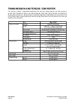
Transmission and Torque Converter
(ZF 4WG-310)
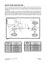
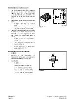
The main pressure valve is limiting the max. control pressure to 16+2 bar (232+29 psi) and releases the
main stream to the converter and lubricating circuit.
In the inlet to the converter, a converter safety valve is installed which protects the converter from high
internal pressure (opening pressure 11 bar (160 psi).
Within the converter, the oil serves to transmit the power according to the well-known hydro-dynamic
principle.
To avoid cavitation, the converter must be always completely filled with oil.
This is achieved by a converter pressure backup valve, rear-mounted to the converter, with an opening
pressure of at least 5 bar (73 psi).
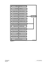
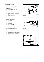
The oil, escaping out of the converter, is directed to a heat exchanger.
From the heat exchanger, the oil is directed to the transmission and there to the lubricating oil circuit, so
that all lubricating points are supplied with cooled oil.
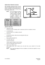
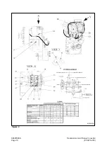
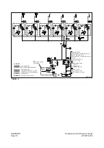
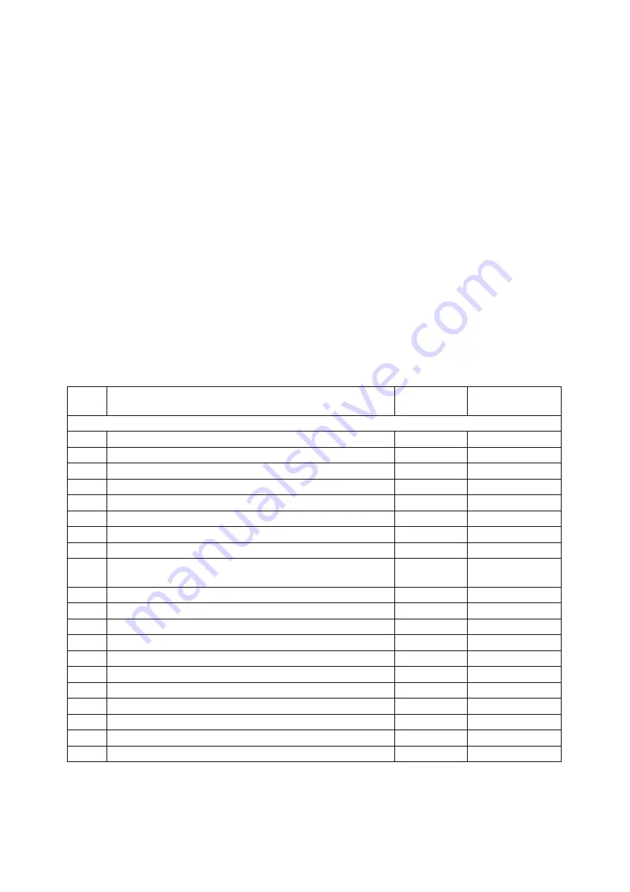
The allocation of the pressure regulators to the single speeds can be seen on the “Schedule of Measuring
Points and Connection 4WG-310” on page 8 and “Oil Circuit Diagram 4WG-310 Forward 1st Speed” on
page 11.
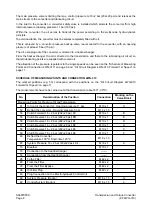
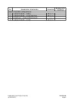
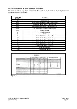
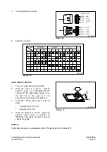
SCHEDULE OF MEASURING POINTS AND CONNECTION 4WG-310
The marked positions (e.g. 53) correspond with the positions on the “Oil Circuit Diagram 4WG-310
Forward 1st Speed” on page 11.
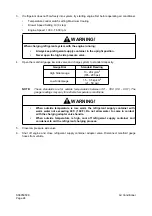
The measurements have to be carried out at hot transmission (about 80
°
- 90
°
C).
No.
Denomination of the Position
Connection
Marking on the
Valve Block
Measuring Points for Pressure Oil and Temperature
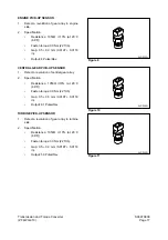
51
In front of the converter - Opening pressure 11 bar
M10 x 1
H
52
Behind the converter - Opening pressure 5 bar
M14 x 1.5
53
Clutch Forward 16 + 2 bar (232+29 psi) KV
M10 x 1
B
55
Clutch Reverse 16 + 2 bar (232+29 psi) KR
M10 x 1
E
56
Clutch Reverse 16 + 2 bar (232+29 psi) K1
M10 x 1
D
57
Clutch Reverse 16 + 2 bar (232+29 psi) K2
M10 x 1
A
58
Clutch Reverse 16 + 2 bar (232+29 psi) K3
M10 x 1
C
60
Clutch Reverse 16 + 2 bar (232+29 psi) K4
M10 x 1
F
63
Behind the Converter
Temperature 100
°
C, Short-time 120
°
C
M14 x 1.5
65
System Pressure 16 + 2 bar (232+29 psi) K4
M10 x 1
K
10
Breather
M10 x 1
15
Connection to the Heat Exchanger
-------
16
Connection from the Heat Exchanger
-------
28
To the Filter
M42 x 2
29
From the Filter
M42 x 2
30
From the Filter Bypass
M42 x 2
36
Oil Filter Plug
M42 x 2
49
Plug Connection on the Electrohydraulic Control Unit
68
System Pressure (Option)
M16 x 1.5
G
69
Control System (Option)
M16 x 1.5
J
Содержание Mega 500-V
Страница 4: ...1SAFETY ...
Страница 41: ...1SPECIFICATIONS ...
Страница 47: ...S0203070K Page 6 Specifications for Mega 500 V ENGINE PERFORMANCE CURVES AHS3720L Figure 2 ...
Страница 55: ...S0203070K Page 14 Specifications for Mega 500 V ...
Страница 56: ...1GENERAL MAINTENANCE ...
Страница 70: ...S0302000 Page 14 General Maintenance Procedures Return to Master Table of Contents ...
Страница 83: ...1UPPER STRUCTURE ...
Страница 85: ...S0403040K Page 2 Counterweight TABLE OF CONTENTS Specifications 3 Counterweight 3 ...
Страница 87: ...S0403040K Page 4 Counterweight ...
Страница 95: ...S0406040K Page 2 Hydraulic Oil Tank TABLE OF CONTENTS General Description 3 Parts List 3 Specifications 4 ...
Страница 98: ...1LOWER STRUCTURE AND CHASSIS ...
Страница 100: ...S0502020K Page 2 Center Joint Articulation Joint TABLE OF CONTENTS General Description 3 Maintenance Standard 4 ...
Страница 104: ...S0502020K Page 6 Center Joint Articulation Joint ...
Страница 105: ...1ENGINE AND DRIVE TRAIN ...
Страница 117: ...S0602170K Page 12 Axle ZF AP 420R Pinion distance must be decreased Figure 5 Figure 6 Figure 7 Figure 8 ...
Страница 118: ...S0602170K Page 13 Axle ZF AP 420R Figure 9 ...
Страница 119: ...S0602170K Page 14 Axle ZF AP 420R ...
Страница 121: ...S0602170K Page 16 Axle ZF AP 420R FINAL DRIVE AP 407 409 Figure 10 ...
Страница 123: ...S0602170K Page 18 Axle ZF AP 420R AP 411 415 Figure 11 ...
Страница 125: ...S0602170K Page 20 Axle ZF AP 420R AP 417 420 Figure 12 ...
Страница 127: ...S0602170K Page 22 Axle ZF AP 420R DIFFERENTIAL VERSION SCREWED BEARING CAPS Differential Carrier CK Figure 13 ...
Страница 129: ...S0602170K Page 24 Axle ZF AP 420R Differential Carrier RK Figure 14 ...
Страница 131: ...S0602170K Page 26 Axle ZF AP 420R Differential Carrier DK ...
Страница 133: ...S0602170K Page 28 Axle ZF AP 420R DIFFERENTIAL VERSION CAST ON BEARING CAPS Differential Carrier DK Figure 15 ...
Страница 135: ...S0602170K Page 30 Axle ZF AP 420R Differential Carrier HK Figure 16 ...
Страница 178: ...S0602170K Page 73 Axle ZF AP 420R ILLUSTRATED TABLE Figure 152 ...
Страница 194: ...S0602170K Page 89 Axle ZF AP 420R ILLUSTRATED TABLE Figure 196 ...
Страница 210: ...S0602170K Page 105 Axle ZF AP 420R ILLUSTRATED TABLE Figure 242 ...
Страница 225: ...S0602170K Page 120 Axle ZF AP 420R ILLUSTRATED TABLE Figure 289 ...
Страница 251: ...S0605050K Page 26 Air Conditioner Return to Master Table of Contents ...
Страница 261: ...S0607080K Page 10 Transmission and Torque Converter ZF 4WG 310 Figure 2 ...
Страница 264: ...S0607080K Page 13 Transmission and Torque Converter ZF 4WG 310 ...
Страница 271: ...S0607080K Page 20 Transmission and Torque Converter ZF 4WG 310 ...
Страница 291: ...S0607080K Page 40 Transmission and Torque Converter ZF 4WG 310 INSTALLATION VIEW INNER SECTION Figure 36 ...
Страница 296: ...S0607080K Page 45 Transmission and Torque Converter ZF 4WG 310 ...
Страница 447: ...S0607900C Page 36 Transmission Error Codes ZF ...
Страница 448: ...1HYDRAULICS ...
Страница 478: ...S0705010 Page 22 Cylinders Return to Master Table of Contents ...
Страница 489: ...S0708460K Page 11 Main Pump Denison T6DMY Series ...
Страница 490: ...S0708460K Page 12 Main Pump Denison T6DMY Series PARTS LIST Figure 8 ...
Страница 504: ...S0708460K Page 26 Main Pump Denison T6DMY Series ...
Страница 508: ...S0708470K Page 4 Steering and Brake Pump Denison T67DB Series PARTS LIST Figure 2 ...
Страница 514: ...S0708470K Page 10 Steering and Brake Pump Denison T67DB Series DISASSEMBLY Figure 5 ...
Страница 521: ...S0708470K Page 17 Steering and Brake Pump Denison T67DB Series ...
Страница 522: ...S0708470K Page 18 Steering and Brake Pump Denison T67DB Series REASSEMBLY Figure 15 ...
Страница 528: ...S0708470K Page 24 Steering and Brake Pump Denison T67DB Series ...
Страница 548: ...S0709476K Page 2 Pilot Control Valve Return to Master Table of Contents ...
Страница 554: ...S0709476K Page 8 Pilot Control Valve Return to Master Table of Contents ...
Страница 557: ...S0709665K Page 3 Flow Amplifier Danfoss GENERAL DESCRIPTION Figure 1 ...
Страница 558: ...S0709665K Page 4 Flow Amplifier Danfoss PARTS LIST Figure 2 ...
Страница 561: ...S0709665K Page 7 Flow Amplifier Danfoss TROUBLESHOOTING TESTING AND ADJUSTMENT Figure 4 Flow Amplifier Circuit ...
Страница 582: ...S0709665K Page 28 Flow Amplifier Danfoss H Shock valve suction valve shown dismantled Figure 63 ...
Страница 609: ...S0709730K Page 7 Power Steering Unit Return to Master Table of Contents ...
Страница 632: ...S0709730K Page 30 Power Steering Unit Return to Master Table of Contents ...
Страница 638: ...S0709750K Page 6 Restriction Valve Return to Master Table of Contents ...
Страница 642: ...S0793060K Page 4 Hydraulic Schematic Mega 500 V Return to Master Table of Contents MEGA 500 V Figure 2 ...
Страница 644: ...S0793060K Page 6 Hydraulic Schematic Mega 500 V Return to Master Table of Contents ...
Страница 645: ...1ELECTRICAL SYSTEM ...
Страница 654: ...S0802190K Page 9 Electrical System Return to Master Table of Contents ...
Страница 658: ...S0802190K Page 13 Electrical System Return to Master Table of Contents ...
Страница 676: ...S0802190K Page 31 Electrical System Return to Master Table of Contents ...
Страница 683: ...S0893060K Page 4 Electrical Schematic Mega 500 V Return to Master Table of Contents MEGA 500 V Figure 2 ...
Страница 684: ...S0893060K Page 5 Electrical Schematic Mega 500 V Return to Master Table of Contents AHS3680L MEGA 500 V ...
Страница 685: ...S0893060K Page 6 Electrical Schematic Mega 500 V Return to Master Table of Contents ...
Страница 686: ...1ATTACHMENTS ...