

S0602170K
Page 21
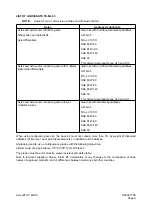
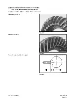
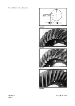
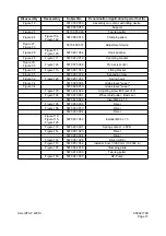
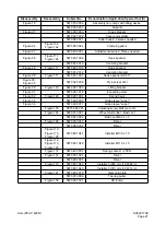
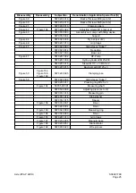
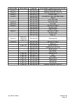
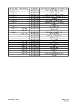
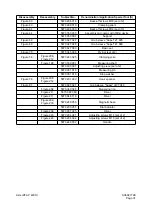
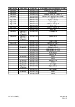
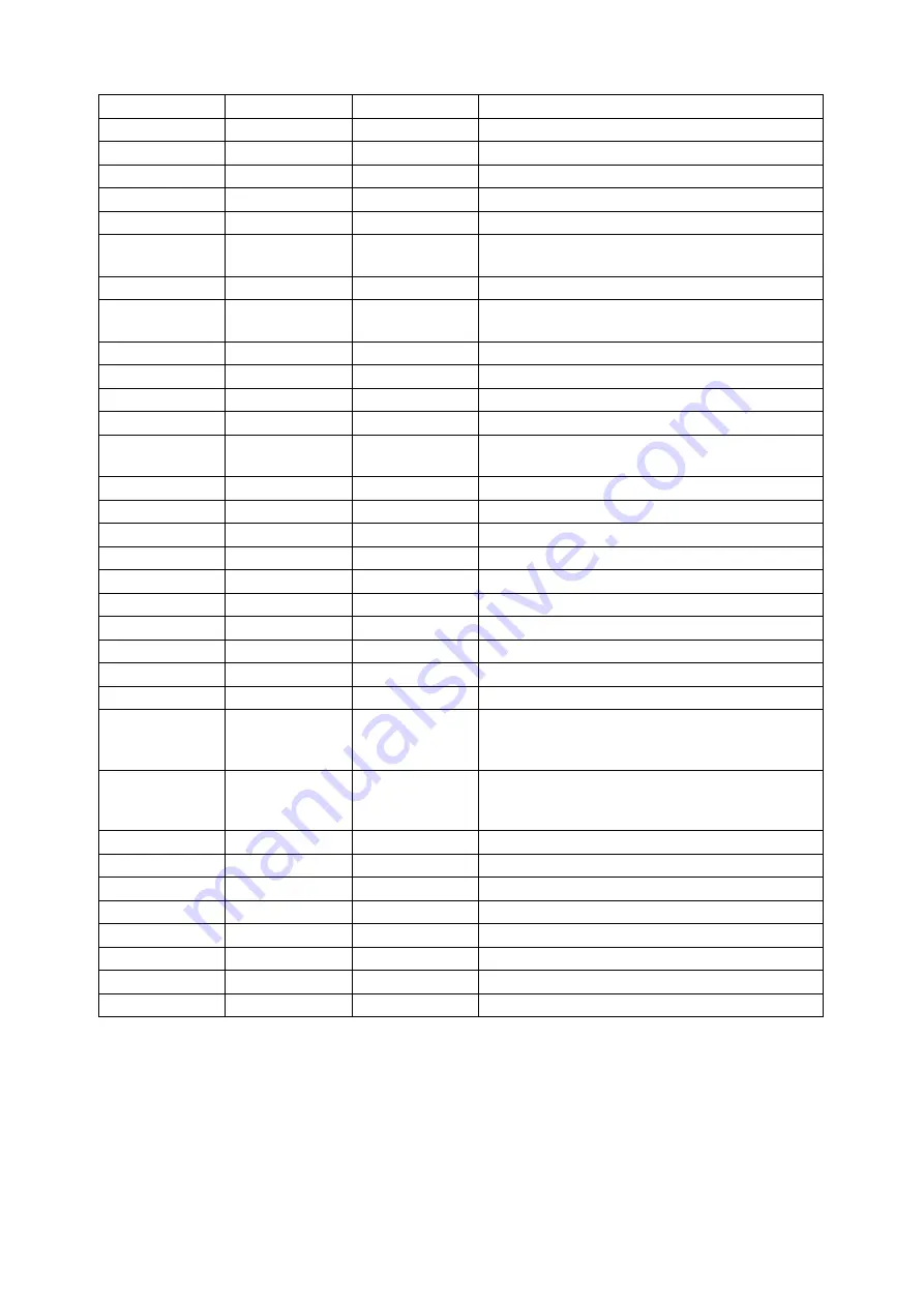
Axle (ZF AP 420R)
Disassembly
Reassembly
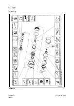
Subject-No.
Denomination /Application Special Tool (S)
Figure 18
5870 350 000
Assembly car compl. with tilting device
5870 350 053
Support
Figure 21
5870 080 030
Cross bracket
5870 027 032
Cover and spindle
5870 080 031
Puller hook # 2 pieces needed
Figure 24
Figure 134,
Figure 142
5870 900 024
Clamping pliers
Figure 27
5870 400 001
Adjustment device 2 Pieces needed
Figure 28
Figure 111,
Figure 125
5870 401 098
Hook spanner
5870 912 012
Centering bracket
Figure 28
Figure 111
5870 401 106
Hook spanner
5870 912 012
Centering bracket
Figure 28
Figure 111
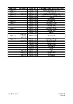
5870 401 097
Hook spanner AP 417
Figure 30,
Figure 35
5870 345 036
Pry bar (set of 2)
Figure 30
Figure 110
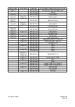
5870 281 033
Lifting bracket
Figure 31
5870 281 016
Expanding claw
Figure 32
Figure 123
5870 281 034
Spring hook
Figure 34
5870 028 008
Grab sleeve "super"
Figure 34
5870 028 011
Grab sleeve "super"
Figure 103
5870 204 045
Adjusting screw M24 (set of 2)
Figure 104
5870 610 001
Wheel stud puller - Basic set
5870 610 002
Basic set M22 x 1.5
Figure 105
5870 050 011
Driver
5870 260 004
Driver
Figure 110,
Figure 115,
Figure 125
5870 651 041
Installer M130 x 1.5
Figure 110,
Figure 115,
Figure 125
5870 651 049
Installer M110 x 1.5
Figure 112
5870 230 007
Spring scale O - 200 N
Figure 114
5870 051 023
Driver
5870 260 004
Driver
Figure 119
5870 651 042
Installer
∅
260 mm (10.2362 in)
5870 651 043
Installer
∅
315 mm (12.4016 in)
Figure 121
5870 654 018
Clamping plate
5870 970 006
Two-leg puller
Figure 150
5870 287 007
HP-Pump
Содержание Mega 500-V
Страница 4: ...1SAFETY ...
Страница 41: ...1SPECIFICATIONS ...
Страница 47: ...S0203070K Page 6 Specifications for Mega 500 V ENGINE PERFORMANCE CURVES AHS3720L Figure 2 ...
Страница 55: ...S0203070K Page 14 Specifications for Mega 500 V ...
Страница 56: ...1GENERAL MAINTENANCE ...
Страница 70: ...S0302000 Page 14 General Maintenance Procedures Return to Master Table of Contents ...
Страница 83: ...1UPPER STRUCTURE ...
Страница 85: ...S0403040K Page 2 Counterweight TABLE OF CONTENTS Specifications 3 Counterweight 3 ...
Страница 87: ...S0403040K Page 4 Counterweight ...
Страница 95: ...S0406040K Page 2 Hydraulic Oil Tank TABLE OF CONTENTS General Description 3 Parts List 3 Specifications 4 ...
Страница 98: ...1LOWER STRUCTURE AND CHASSIS ...
Страница 100: ...S0502020K Page 2 Center Joint Articulation Joint TABLE OF CONTENTS General Description 3 Maintenance Standard 4 ...
Страница 104: ...S0502020K Page 6 Center Joint Articulation Joint ...
Страница 105: ...1ENGINE AND DRIVE TRAIN ...
Страница 117: ...S0602170K Page 12 Axle ZF AP 420R Pinion distance must be decreased Figure 5 Figure 6 Figure 7 Figure 8 ...
Страница 118: ...S0602170K Page 13 Axle ZF AP 420R Figure 9 ...
Страница 119: ...S0602170K Page 14 Axle ZF AP 420R ...
Страница 121: ...S0602170K Page 16 Axle ZF AP 420R FINAL DRIVE AP 407 409 Figure 10 ...
Страница 123: ...S0602170K Page 18 Axle ZF AP 420R AP 411 415 Figure 11 ...
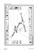
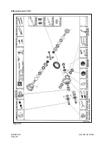
Страница 125: ...S0602170K Page 20 Axle ZF AP 420R AP 417 420 Figure 12 ...
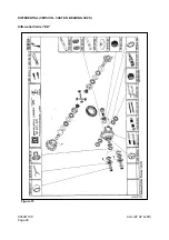
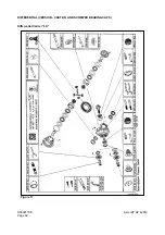
Страница 127: ...S0602170K Page 22 Axle ZF AP 420R DIFFERENTIAL VERSION SCREWED BEARING CAPS Differential Carrier CK Figure 13 ...
Страница 129: ...S0602170K Page 24 Axle ZF AP 420R Differential Carrier RK Figure 14 ...
Страница 131: ...S0602170K Page 26 Axle ZF AP 420R Differential Carrier DK ...
Страница 133: ...S0602170K Page 28 Axle ZF AP 420R DIFFERENTIAL VERSION CAST ON BEARING CAPS Differential Carrier DK Figure 15 ...
Страница 135: ...S0602170K Page 30 Axle ZF AP 420R Differential Carrier HK Figure 16 ...
Страница 178: ...S0602170K Page 73 Axle ZF AP 420R ILLUSTRATED TABLE Figure 152 ...
Страница 194: ...S0602170K Page 89 Axle ZF AP 420R ILLUSTRATED TABLE Figure 196 ...
Страница 210: ...S0602170K Page 105 Axle ZF AP 420R ILLUSTRATED TABLE Figure 242 ...
Страница 225: ...S0602170K Page 120 Axle ZF AP 420R ILLUSTRATED TABLE Figure 289 ...
Страница 251: ...S0605050K Page 26 Air Conditioner Return to Master Table of Contents ...
Страница 261: ...S0607080K Page 10 Transmission and Torque Converter ZF 4WG 310 Figure 2 ...
Страница 264: ...S0607080K Page 13 Transmission and Torque Converter ZF 4WG 310 ...
Страница 271: ...S0607080K Page 20 Transmission and Torque Converter ZF 4WG 310 ...
Страница 291: ...S0607080K Page 40 Transmission and Torque Converter ZF 4WG 310 INSTALLATION VIEW INNER SECTION Figure 36 ...
Страница 296: ...S0607080K Page 45 Transmission and Torque Converter ZF 4WG 310 ...
Страница 447: ...S0607900C Page 36 Transmission Error Codes ZF ...
Страница 448: ...1HYDRAULICS ...
Страница 478: ...S0705010 Page 22 Cylinders Return to Master Table of Contents ...
Страница 489: ...S0708460K Page 11 Main Pump Denison T6DMY Series ...
Страница 490: ...S0708460K Page 12 Main Pump Denison T6DMY Series PARTS LIST Figure 8 ...
Страница 504: ...S0708460K Page 26 Main Pump Denison T6DMY Series ...
Страница 508: ...S0708470K Page 4 Steering and Brake Pump Denison T67DB Series PARTS LIST Figure 2 ...
Страница 514: ...S0708470K Page 10 Steering and Brake Pump Denison T67DB Series DISASSEMBLY Figure 5 ...
Страница 521: ...S0708470K Page 17 Steering and Brake Pump Denison T67DB Series ...
Страница 522: ...S0708470K Page 18 Steering and Brake Pump Denison T67DB Series REASSEMBLY Figure 15 ...
Страница 528: ...S0708470K Page 24 Steering and Brake Pump Denison T67DB Series ...
Страница 548: ...S0709476K Page 2 Pilot Control Valve Return to Master Table of Contents ...
Страница 554: ...S0709476K Page 8 Pilot Control Valve Return to Master Table of Contents ...
Страница 557: ...S0709665K Page 3 Flow Amplifier Danfoss GENERAL DESCRIPTION Figure 1 ...
Страница 558: ...S0709665K Page 4 Flow Amplifier Danfoss PARTS LIST Figure 2 ...
Страница 561: ...S0709665K Page 7 Flow Amplifier Danfoss TROUBLESHOOTING TESTING AND ADJUSTMENT Figure 4 Flow Amplifier Circuit ...
Страница 582: ...S0709665K Page 28 Flow Amplifier Danfoss H Shock valve suction valve shown dismantled Figure 63 ...
Страница 609: ...S0709730K Page 7 Power Steering Unit Return to Master Table of Contents ...
Страница 632: ...S0709730K Page 30 Power Steering Unit Return to Master Table of Contents ...
Страница 638: ...S0709750K Page 6 Restriction Valve Return to Master Table of Contents ...
Страница 642: ...S0793060K Page 4 Hydraulic Schematic Mega 500 V Return to Master Table of Contents MEGA 500 V Figure 2 ...
Страница 644: ...S0793060K Page 6 Hydraulic Schematic Mega 500 V Return to Master Table of Contents ...
Страница 645: ...1ELECTRICAL SYSTEM ...
Страница 654: ...S0802190K Page 9 Electrical System Return to Master Table of Contents ...
Страница 658: ...S0802190K Page 13 Electrical System Return to Master Table of Contents ...
Страница 676: ...S0802190K Page 31 Electrical System Return to Master Table of Contents ...
Страница 683: ...S0893060K Page 4 Electrical Schematic Mega 500 V Return to Master Table of Contents MEGA 500 V Figure 2 ...
Страница 684: ...S0893060K Page 5 Electrical Schematic Mega 500 V Return to Master Table of Contents AHS3680L MEGA 500 V ...
Страница 685: ...S0893060K Page 6 Electrical Schematic Mega 500 V Return to Master Table of Contents ...
Страница 686: ...1ATTACHMENTS ...