


S0103010K
Page 21
Wheel Loader Safety
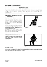
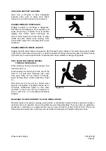
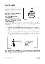
USE SOLID SUPPORT BLOCKING
Never rely on lift jacks or other inadequate
supports when work is being done. Block
wheels fore and aft to prevent any movement.
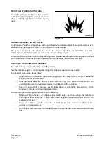
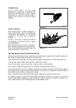
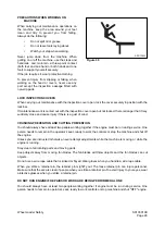
DIGGING BENEATH OVERHANGS
Digging beneath an overhang is dangerous.
Overhand could collapse on top of operator and
cause serious injury or death. Go on to another
digging area before steep overhangs are
formed. Know height and reach limits of wheel
loader and plan ahead while working. Park
wheel loader away from overhangs before work
shutdown.
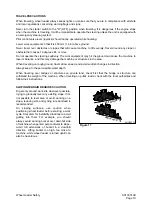
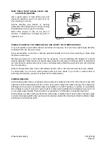
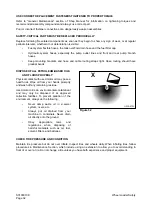
DIGGING BENEATH WHEEL LOADER
Digging beneath wheel loader is dangerous. Earth beneath could collapse. This could cause wheel loader
to tip, which could cause serious injury or death to operator. Working around deep pits, trenching or along
high walls may require support blocks, especially after heavy rainfalls or during spring thaws.
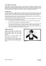
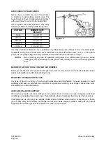
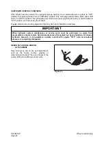
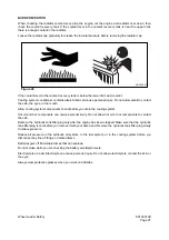
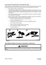
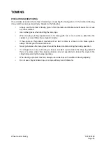
STAY ALERT FOR PEOPLE MOVING
THROUGH WORK AREA
When loading a truck you should always know
where the driver is.
Avoid loading over the cab of a truck even if the
driver is in a safe spot. Someone else could
have gone inside, for any number of reasons.
Avoid working where unseen passersby might
be.
Slow down work cycle and use slower travel
speeds in congested or populated areas. Use a
commonly understood signal so that other
members of work crew can warn operator to
slow or halt work in an impending hazardous
situation.
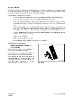
BE AWARE OF AND CONFORM TO LOCAL REGULATIONS
Minimum levels of insurance coverage, work permits or certification, physical barriers around work-site or
restricted hours of operation may be mandated by governing authorities. There may also be guidelines,
standards or restrictions on equipment that may be used to perform certain kinds of work. Check and
follow all local requirements, which may also be related to below ground hazards and power lines.
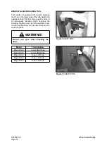
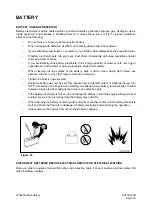
HDO1042L
Figure 19
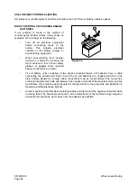
HAOA171L
Figure 20
Содержание Mega 500-V
Страница 4: ...1SAFETY ...
Страница 41: ...1SPECIFICATIONS ...
Страница 47: ...S0203070K Page 6 Specifications for Mega 500 V ENGINE PERFORMANCE CURVES AHS3720L Figure 2 ...
Страница 55: ...S0203070K Page 14 Specifications for Mega 500 V ...
Страница 56: ...1GENERAL MAINTENANCE ...
Страница 70: ...S0302000 Page 14 General Maintenance Procedures Return to Master Table of Contents ...
Страница 83: ...1UPPER STRUCTURE ...
Страница 85: ...S0403040K Page 2 Counterweight TABLE OF CONTENTS Specifications 3 Counterweight 3 ...
Страница 87: ...S0403040K Page 4 Counterweight ...
Страница 95: ...S0406040K Page 2 Hydraulic Oil Tank TABLE OF CONTENTS General Description 3 Parts List 3 Specifications 4 ...
Страница 98: ...1LOWER STRUCTURE AND CHASSIS ...
Страница 100: ...S0502020K Page 2 Center Joint Articulation Joint TABLE OF CONTENTS General Description 3 Maintenance Standard 4 ...
Страница 104: ...S0502020K Page 6 Center Joint Articulation Joint ...
Страница 105: ...1ENGINE AND DRIVE TRAIN ...
Страница 117: ...S0602170K Page 12 Axle ZF AP 420R Pinion distance must be decreased Figure 5 Figure 6 Figure 7 Figure 8 ...
Страница 118: ...S0602170K Page 13 Axle ZF AP 420R Figure 9 ...
Страница 119: ...S0602170K Page 14 Axle ZF AP 420R ...
Страница 121: ...S0602170K Page 16 Axle ZF AP 420R FINAL DRIVE AP 407 409 Figure 10 ...
Страница 123: ...S0602170K Page 18 Axle ZF AP 420R AP 411 415 Figure 11 ...
Страница 125: ...S0602170K Page 20 Axle ZF AP 420R AP 417 420 Figure 12 ...
Страница 127: ...S0602170K Page 22 Axle ZF AP 420R DIFFERENTIAL VERSION SCREWED BEARING CAPS Differential Carrier CK Figure 13 ...
Страница 129: ...S0602170K Page 24 Axle ZF AP 420R Differential Carrier RK Figure 14 ...
Страница 131: ...S0602170K Page 26 Axle ZF AP 420R Differential Carrier DK ...
Страница 133: ...S0602170K Page 28 Axle ZF AP 420R DIFFERENTIAL VERSION CAST ON BEARING CAPS Differential Carrier DK Figure 15 ...
Страница 135: ...S0602170K Page 30 Axle ZF AP 420R Differential Carrier HK Figure 16 ...
Страница 178: ...S0602170K Page 73 Axle ZF AP 420R ILLUSTRATED TABLE Figure 152 ...
Страница 194: ...S0602170K Page 89 Axle ZF AP 420R ILLUSTRATED TABLE Figure 196 ...
Страница 210: ...S0602170K Page 105 Axle ZF AP 420R ILLUSTRATED TABLE Figure 242 ...
Страница 225: ...S0602170K Page 120 Axle ZF AP 420R ILLUSTRATED TABLE Figure 289 ...
Страница 251: ...S0605050K Page 26 Air Conditioner Return to Master Table of Contents ...
Страница 261: ...S0607080K Page 10 Transmission and Torque Converter ZF 4WG 310 Figure 2 ...
Страница 264: ...S0607080K Page 13 Transmission and Torque Converter ZF 4WG 310 ...
Страница 271: ...S0607080K Page 20 Transmission and Torque Converter ZF 4WG 310 ...
Страница 291: ...S0607080K Page 40 Transmission and Torque Converter ZF 4WG 310 INSTALLATION VIEW INNER SECTION Figure 36 ...
Страница 296: ...S0607080K Page 45 Transmission and Torque Converter ZF 4WG 310 ...
Страница 447: ...S0607900C Page 36 Transmission Error Codes ZF ...
Страница 448: ...1HYDRAULICS ...
Страница 478: ...S0705010 Page 22 Cylinders Return to Master Table of Contents ...
Страница 489: ...S0708460K Page 11 Main Pump Denison T6DMY Series ...
Страница 490: ...S0708460K Page 12 Main Pump Denison T6DMY Series PARTS LIST Figure 8 ...
Страница 504: ...S0708460K Page 26 Main Pump Denison T6DMY Series ...
Страница 508: ...S0708470K Page 4 Steering and Brake Pump Denison T67DB Series PARTS LIST Figure 2 ...
Страница 514: ...S0708470K Page 10 Steering and Brake Pump Denison T67DB Series DISASSEMBLY Figure 5 ...
Страница 521: ...S0708470K Page 17 Steering and Brake Pump Denison T67DB Series ...
Страница 522: ...S0708470K Page 18 Steering and Brake Pump Denison T67DB Series REASSEMBLY Figure 15 ...
Страница 528: ...S0708470K Page 24 Steering and Brake Pump Denison T67DB Series ...
Страница 548: ...S0709476K Page 2 Pilot Control Valve Return to Master Table of Contents ...
Страница 554: ...S0709476K Page 8 Pilot Control Valve Return to Master Table of Contents ...
Страница 557: ...S0709665K Page 3 Flow Amplifier Danfoss GENERAL DESCRIPTION Figure 1 ...
Страница 558: ...S0709665K Page 4 Flow Amplifier Danfoss PARTS LIST Figure 2 ...
Страница 561: ...S0709665K Page 7 Flow Amplifier Danfoss TROUBLESHOOTING TESTING AND ADJUSTMENT Figure 4 Flow Amplifier Circuit ...
Страница 582: ...S0709665K Page 28 Flow Amplifier Danfoss H Shock valve suction valve shown dismantled Figure 63 ...
Страница 609: ...S0709730K Page 7 Power Steering Unit Return to Master Table of Contents ...
Страница 632: ...S0709730K Page 30 Power Steering Unit Return to Master Table of Contents ...
Страница 638: ...S0709750K Page 6 Restriction Valve Return to Master Table of Contents ...
Страница 642: ...S0793060K Page 4 Hydraulic Schematic Mega 500 V Return to Master Table of Contents MEGA 500 V Figure 2 ...
Страница 644: ...S0793060K Page 6 Hydraulic Schematic Mega 500 V Return to Master Table of Contents ...
Страница 645: ...1ELECTRICAL SYSTEM ...
Страница 654: ...S0802190K Page 9 Electrical System Return to Master Table of Contents ...
Страница 658: ...S0802190K Page 13 Electrical System Return to Master Table of Contents ...
Страница 676: ...S0802190K Page 31 Electrical System Return to Master Table of Contents ...
Страница 683: ...S0893060K Page 4 Electrical Schematic Mega 500 V Return to Master Table of Contents MEGA 500 V Figure 2 ...
Страница 684: ...S0893060K Page 5 Electrical Schematic Mega 500 V Return to Master Table of Contents AHS3680L MEGA 500 V ...
Страница 685: ...S0893060K Page 6 Electrical Schematic Mega 500 V Return to Master Table of Contents ...
Страница 686: ...1ATTACHMENTS ...