background image


120

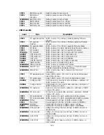
INFO 

BBM status good 

Battery backup module is good 

INFO 

BBM status 
charging 

Battery backup module is charging 

WARNING  BBM status fail 

Battery backup module is failed 

INFO 

BBM enabled 

Battery backup feature is <string>. 

INFO 

BBM inserted 

Battery backup module is inserted 

INFO 

BBM removed 

Battery backup module is removed 


JBOD events


Level Type 

Description 


INFO 

PD upgrade started

JBOD <name> PD [<string>] starts upgrading firmware 
process. 

INFO 

PD upgrade 

finished 

JBOD <name> PD [<string>] finished upgrading firmware 

process. 

WARNING  PD upgrade failed 

JBOD <name> PD [<string>] upgrade firmware failed. 

INFO 

PD freed 

JBOD <name> PD <slot> has been freed from RG <name>. 

INFO 

PD inserted 

JBOD <name> disk <slot> is inserted into system. 

Warning 

PD removed 

JBOD <name> disk <slot> is removed from system. 

ERROR 

HDD read error 

JBOD <name> disk <slot> read block error 

ERROR 

HDD write error 

JBOD <name> disk <slot> write block error 

ERROR 

HDD error 

JBOD <name> disk <slot> is disabled. 

ERROR 

HDD IO timeout 

JBOD <name> disk <slot> gets no response 

INFO 

JBOD inserted 

JBOD <name> is inserted into system 

WARNING  JBOD removed 

JBOD <name> is removed from system 

WARNING  SMART T.E.C 

JBOD <name> disk <slot>: S.M.A.R.T. Threshold Exceed 

Condition occurred for attribute <string> 

WARNING  SMART fail 

JBOD <name> disk <slot>: Failure to get S.M.A.R.T 

information 

INFO 

PD dedicated spare

Assign JBOD <name> PD <slot> to be the dedicated spare 

disk of RG <name>. 

INFO 

PD global spare 

Assign JBOD <name> PD <slot> to Global Spare Disks. 

ERROR 

Config read fail 

Config read error occurred at LBA <address>-<address> of 
JBOD <name> PD <slot>. 

ERROR 

Config write fail 

Config write error occurred at LBA <address>-<address> of 

JBOD <name> PD <slot>. 

WARNING  PD read error 

Read error occurred at LBA <address>-<address> of JBOD 

<name> PD <slot>. 

WARNING  PD write error 

Write error occurred at LBA <address>-<address> of JBOD 
<name> PD <slot>. 

INFO 

PD scrub started 

JBOD <name> PD <slot> starts disk scrubbing process. 

INFO 

PD scrub completed JBOD <name> PD <slot> completed disk scrubbing process. 

WARNING  PS fail 

Power Supply of <string> in JBOD <name> is FAIL 

INFO 

PS normal 

Power Supply of <string> in JBOD <name> is NORMAL 

WARNING  FAN fail 

Cooling fan of <string> in JBOD <name> is FAIL 

INFO 

FAN normal 

Cooling fan of <string> in JBOD <name> is NORMAL 

WARNING  Volt warn OV 

Voltage of <string> read as <string> in JBOD <name> is 

WARN OVER 

WARNING  Volt warn UV 

Voltage of <string> read as <string> in JBOD <name> is 

WARN UNDER 

WARNING  Volt crit OV 

Voltage of <string> read as <string> in JBOD <name> is 
CRIT OVER 

WARNING  Volt crit UV 

Voltage of <item> read as <string> in JBOD <name> is 

CRIT UNDER 

Содержание DSN-6120

Страница 1: ...1 D Link iSCSI IP SAN storage GbE iSCSI to SATA II SAS RAID IP SAN storage DSN 6110 DSN 6120 User Manual Version 1 0 ...

Страница 2: ...nformation and specification herein are subject to change without notice For any update information please visit www dlink com Model comparison DSN 6100 series adopt 2U12 form factor for all models DSN 61x0 IP SAN storages stand for the following models DSN 6120 Dual controllers DSN 6110 Single controller can be upgradable to dual mode The dual controller specific functions such as dual active cac...

Страница 3: ...3 4 Rear view 21 2 4 Install battery backup module 23 2 5 Deployment 25 Chapter 3 Quick setup 27 3 1 Management interfaces 27 3 1 1 Serial console 27 3 1 2 Remote control 27 3 1 3 Web UI 27 3 2 How to use the system quickly 30 3 2 1 Quick installation 30 3 2 2 Volume creation wizard 32 Chapter 4 Configuration 35 4 1 Web UI management interface hierarchy 35 4 2 System configuration 36 4 2 1 System ...

Страница 4: ... 7 Home Logout Mute 79 4 7 1 Home 79 4 7 2 Logout 79 4 7 3 Mute 79 Chapter 5 Advanced operations 80 5 1 Volume rebuild 80 5 2 RG migration 82 5 3 VD extension 83 5 4 Snapshot 84 5 4 1 Create snapshot volume 85 5 4 2 Auto snapshot 86 5 4 3 Rollback 87 5 4 4 Snapshot constraint 87 5 5 Disk roaming 89 5 6 VD clone 90 5 7 SAS JBOD expansion 97 5 7 1 Connecting JBOD 97 5 7 2 Upgrade firmware of JBOD 97...

Страница 5: ...5 6 2 Event notifications 117 A Certification list 123 B Microsoft iSCSI initiator 126 C From single controller to Dual controller 132 ...

Страница 6: ...n It provides consistent and instant copies of data volumes without any system downtime Snapshot on the box can keep up to 32 snapshots for one logical volume Rollback feature is provided for restoring the previous snapshot data easily while continuously using the volume for further data access The data access which includes read write is working as usual without any impact to end users The on the...

Страница 7: ... Auto disk spin down Advanced cooling RAID Level RAID 0 1 0 1 3 5 6 10 30 50 60 and JBOD N way mirror Compatibility Support multiple OSes applications iSCSI HBA software initiators and etc Virtualization VMWare Hyper V Citrix Data Protection Snapshot Read only and Writeable Storage base Replication Connection Availability Load balancing and failover support on the iSCSI GbE ports Dimension W x D x...

Страница 8: ...D level attribute VD Virtual Disk Each RD could be divided into several VDs The VDs from one RG have the same RAID level but may have different volume capacity LUN Logical Unit Number A logical unit number LUN is a unique identifier which enables it to differentiate among separate devices each one is a logical unit GUI Graphic User Interface RAID cell When creating a RAID group with a compound RAI...

Страница 9: ...ted spare disks for any rebuilding purpose GS Global Spare disks GS is shared for rebuilding purpose If some RGs need to use the global spare disks for rebuilding they could get the spare disks out from the common spare disks pool for such requirement DG DeGraded mode Not all of the array s member disks are functioning but the array is able to respond to application read and write requests to its ...

Страница 10: ...2 RAID levels There are different RAID levels with different degree of data protection data availability and performance to host environment The description of RAID levels are on the following RAID 0 Disk striping RAID 0 needs at least one hard drive RAID 1 Disk mirroring over two disks RAID 1 needs at least two hard drives N way mirror Extension to RAID 1 level It has N copies of the disk RAID 3 ...

Страница 11: ... RAID level attribute Each RG can be divided into several VDs The VDs in one RG share the same RAID level but may have different volume capacity All VDs share the CV Cache Volume to execute the data transaction LUN Logical Unit Number is an unique identifier in which users can access through SCSI commands Figure 1 2 3 1 1 3 iSCSI concepts iSCSI Internet SCSI is a protocol which encapsulates SCSI S...

Страница 12: ... the host side either an iSCSI HBA or iSCSI SW initiator The target is the storage device itself or an appliance which controls and serves volumes or virtual volumes The target is the device which performs SCSI command or bridge to an attached storage device Figure 1 3 1 The host side needs an iSCSI initiator The initiator is a driver which handles the SCSI traffic over iSCSI The initiator can be ...

Страница 13: ...oup open iscsi topics Open iSCSI Wiki http www open iscsi org cgi bin wiki pl 3 ATTO iSCSI initiator is available for Mac Website http www attotech com xtend html 4 Solaris iSCSI initiator Version Solaris 10 u6 10 08 1 4 IP SAN storage specifications 1 4 1 Technical specifications Controller features 1 Dual active configuration support only for DSN 6120 2 Better performance when comparing to other...

Страница 14: ...D level 0 1 0 1 3 5 6 10 30 50 60 JBOD and N way mirror 2 Up to 1024 logical volumes in the system 3 Up to 32 PDs can be included in one volume group 4 Global and dedicated hot spare disks 5 Write through or write back cache policy for different application usage 6 Multiple RAID volumes support 7 Configurable RAID stripe size 8 Online volume expansion 9 Instant RAID volume availability 10 Auto vol...

Страница 15: ... 2 Notification via Email SNMP trap Browser pop up windows Syslog Windows Messenger 3 iSNS support 4 DHCP support iSCSI features 1 iSCSI jumbo frame support 2 Header Data digest support 3 CHAP authentication enabled 4 Load balancing and failover through MPIO MC S Trunking and LACP 5 Up to 32 multiple nodes support 6 VLAN support Host connection 1 4x GbE ports DSN 6110 8 x GbE ports DSN 6120 2 Host...

Страница 16: ...This device has been shown to be in compliance with and was tested in accordance with the measurement procedures specified in the Standards and Specifications listed below and as indicated in the measurement report number xxxxxxxx F Technical Standard FCC Part 15 Class A Verification IC ICES 003 CE statement This device has been shown to be in compliance with and was tested in accordance with the ...

Страница 17: ...oncern E Reliable Earthing Reliable earthing of rack mounted equipment should be maintained Particular attention should be given to supply connections other than direct connections to the branch circuit e g use of power strips Caution The main purpose of the handles is for rack mount use only Do not use the handles to carry or transport the systems The ITE is not intended to be installed and used ...

Страница 18: ...CSI HBA 2 CAT 5e or CAT 6 network cables for management port and iSCSI data ports 3 Prepare storage system configuration plan 4 Prepare management port and iSCSI data ports network information When using static IP please prepare static IP addresses subnet mask and default gateway 5 Gigabit switches recommended Or Gigabit switches with LCAP Trunking optional 6 CHAP security information including CH...

Страница 19: ...t logs are saved to drives in these slots If no drives are fitted the event logs will be lost in the event of a system reboot 2 3 2 Front LED lights There are three LED lights on the left frame bar Figure 2 3 2 1 LED lights description Power LED Green Power on Off Power off Status LED Red System is failure Off System is good Access LED Blue Host is accessing Off Host is no access ...

Страница 20: ...u purchased a solution populated with drives To install SAS or SATA drives with no Bridge Board use the front mounting holes To install SATA drives with Bridge Board DSN 654 fit the Bridge Board first Then install the drive using the rear mounting holes ...

Страница 21: ...HDD power LED Green HDD is inserted and good Off No HDD HDD access LED Blue blinking HDD is accessing Off No HDD HDD tray handhold Latch for tray kit removal 2 3 4 Rear view Figure 2 3 4 1 DSN 6120 PSU and Fan module description Controller 2 ...

Страница 22: ... module FAN3 FAN4 Power supply unit PSU1 Fan module FAN1 FAN2 Figure 2 3 4 2 DSN 6110 PSU and Fan module description Controller Power supply unit PSU2 Fan module FAN3 FAN4 Power supply unit PSU1 Fan module FAN1 FAN2 Figure 2 3 4 3 DSN 6110 6120 ...

Страница 23: ...isks Off No data on the cache BBM LED Green BBM installed and powered Off No BBM BBM Status Button When the system power is off press the BBM status button if the BBM LED is Green then the BBM still has power to keep data on the cache If not then the BBM power is ran out and cannot keep the data on the cache anymore Management port Console port RS 232 port for UPS SAS JBOD expansion port Power swi...

Страница 24: ...24 1 Shutdown IP SAN storage then power off 2 Remove the cover of battery backup module 3 Insert the battery backup module Figure 2 4 1 4 Tighten the screws up 5 Power on BBM will work Figure 2 4 2 ...

Страница 25: ...5 2 DSN 6110 1 Setup the hardware connection before power on servers Connect console cable management port cable and iSCSI data port cables in advance 2 In addition installing an iSNS server is recommended for dual controller system 3 Power on DSN 6110 6120 and DSN 6020 optional first and then power on hosts and iSNS server ...

Страница 26: ...hen MPIO should be setup automatically only for DSN 6120 Tips iSNS server is recommended for dual controller system For better data service availability all the connections among host servers GbE switches and the dual controllers are recommended as redundant as below Figure 2 5 3 only for DSN 6120 ...

Страница 27: ...assword 123456 3 1 2 Remote control SSH secure shell software is required for remote login The SSH client software is available at the following web site SSH Tectia Client http www ssh com PuTTY http www chiark greenend org uk Host name 192 168 0 32 Default IP Login name admin Default password 123456 Tips D Link product supports SSH for remote control only For using SSH the IP address and password...

Страница 28: ...ter login choose the functions which lists on the left side of window to make any configuration Figure 3 1 4 2 There are seven indicators and three icons at the top right corner Figure 3 1 4 3 Indicator description RAID light Green RAID works well Red RAID fails ...

Страница 29: ...ls Dual controller light Green Both controller 1 and controller 2 are present and well Orange The system is degraded and there is only 1 controller alive and well Return to home page Logout the management web UI Mute alarm beeper Tips If the status indicators in Internet Explorer IE are displayed in gray but not in blinking red please enable Internet Options Advanced Play animations in webpages op...

Страница 30: ... Quick installation Please make sure that there are some free drives installed in this system SAS drives are recommended Please check the hard drive details in Volume configuration Physical disk Figure 3 2 1 1 Step1 Click the Quick installation menu item follow the steps to set up system name and date time Figure 3 2 1 2 ...

Страница 31: ...ep2 Confirm the management port IP address and DNS and then click Next Figure 3 2 1 3 Step 3 Set up the data port IP and click Next Figure 3 2 1 4 Step 4 Set up the RAID level and volume size and click Next ...

Страница 32: ... Volume creation wizard Volume create wizard has a smarter policy When the system is inserted with some HDDs Volume create wizard lists all possibilities and sizes in different RAID levels it will use all available HDDs for RAID level depends on which user chooses When system has ...

Страница 33: ...oses RAID 5 and the controller has 12 200G 4 80G HDDs inserted If we use all 16 HDDs for a RAID 5 and then the maximum size of volume is 1200G 80G 15 By the wizard we do smarter check and find out the most efficient way of using HDDs The wizard only uses 200G HDDs Volume size is 200G 11 2200G the volume size is bigger and fully uses HDD capacity Step 1 Select Volume create wizard and then choose t...

Страница 34: ... to the default number Then click Next Figure 3 2 2 3 Step 4 Confirmation page Click Finish if all setups are correct Then a VD will be created Step 5 Done The system is available now Figure 3 2 2 4 Figure 3 2 2 4 A virtual disk of RAID 0 is created and is named by system itself ...

Страница 35: ...ate Modify user information Delete Volume configuration Physical disk Set Free disk Set Global spare Set Dedicated spare Upgrade Disk Scrub Turn on off the indication LED More information RAID group Create Migrate Activate Deactivate Parity check Delete Set preferred owner Set disk property More information Virtual disk Create Extend Parity check Delete Set property Attach LUN Detach LUN List LUN ...

Страница 36: ...wn Reboot Shutdown Quick installation Step 1 Step 2 Step 3 Step 4 Confirm Volume creation wizard Step 1 Step 2 Step 3 Confirm 4 2 System configuration System configuration is designed for setting up the System setting Network setting Login setting Mail setting and Notification setting Figure 4 2 1 4 2 1 System setting System setting can setup system name and date Default System name is composed of...

Страница 37: ...default setting is DHCP User can change the HTTP HTTPS and SSH port number when the default port number is not allowed on host server Figure 4 2 2 1 4 2 3 Login setting Login setting can set single admin auto logout time and admin user password The single admin is to prevent multiple users access the same system in the same time 1 Auto logout The options are 1 Disabled 2 5 minutes 3 30 minutes 4 1...

Страница 38: ...ation Some mail servers would check Mail from address and need authentication for anti spam Please fill the necessary fields and click Send test mail to test whether email functions are available User can also select which levels of event logs are needed to be sent via Mail Default setting only enables ERROR and WARNING event logs Please also make sure the DNS server IP is well setup so the event ...

Страница 39: ...gure 4 2 4 1 4 2 5 Notification setting Notification setting can set up SNMP trap for alerting via SNMP pop up message via Windows messenger not MSN alert via syslog protocol and event log filter for web UI ...

Страница 40: ...must enable the service Messenger in Windows Start Control Panel Administrative Tools Services Messenger and then event logs can be received It allows up to 3 messenger addresses User can choose the event log levels and default setting enables the WARNING and ERROR event logs Using System log server user can choose the facility and the event log level The default port of syslog is 514 The default ...

Страница 41: ...transmit data Each of them must be assigned to an IP address and be set up in multi homed mode or the link aggregation trunking mode has been set up When there are multiple data ports setting up in link aggregation or trunking mode all the data ports share single address Figure 4 3 1 1 Figure 4 3 1 1 There are 4 iSCSI data ports on each controller 4 data ports are set with static IP IP settings Us...

Страница 42: ...P The following is the description of multi homed trunking LACP functions 1 Multi homed Default mode Each of iSCSI data port is connected by itself and is not link aggregation and trunking This function is also for Multipath functions Select this mode can also remove the setting of Trunking LACP in same time 2 Trunking defines the use of multiple iSCSI data ports in parallel to increase the link s...

Страница 43: ...1 3 There are 4 iSCSI data ports on each controller select at least two NICs for link aggregation Figure 4 3 1 4 For example LAN1 and LAN2 are set as Trunking mode LAN3 and LAN4 are set as LACP mode To remove Trunking LACP setting check the gray button of LAN port click Delete link aggregation Then it will pop up a message to confirm Ping host User can ping the corresponding host data port from th...

Страница 44: ...tocol allows automated discovery management and configuration of iSCSI devices on a TCP IP network Using iSNS it needs to install an iSNS server in SAN Add an iSNS server IP address into iSNS server lists in order that iSCSI initiator service can send queries The entity name can be changed Figure 4 3 2 1 4 3 3 Node Node can view the target name for iSCSI initiator DSN 6110 6120 supports up to 32 m...

Страница 45: ... in which the authentication server sends the client a key to be used for encrypting the username and password CHAP enables the username and password to transmit in an encrypted form for protection To use CHAP authentication please follow the procedures 1 Select one of 32 default nodes from one controller 2 Check the gray button of OP column click Authenticate 3 Select CHAP Figure 4 3 3 2 4 Click ...

Страница 46: ...used It s a multi option it can be one or more If choosing none CHAP can not work Figure 4 3 3 4 8 Click OK 9 In Authenticate of OP page select None to disable CHAP Change portal Users can change the portals belonging to the device node of each controller 1 Check the gray button of OP column next to one device node 2 Select Change portal 3 Choose the portals for the controller 4 Click OK to confir...

Страница 47: ... same CHAP account Otherwise user cannot login 4 3 4 Session Session can display current iSCSI session and connection information including the following items 1 TSIH target session identifying handle 2 Host Initiator Name 3 Controller Target Name 4 InitialR2T Initial Ready to Transfer 5 Immed data Immediate data 6 MaxDataOutR2T Maximum Data Outstanding Ready to Transfer 7 MaxDataBurstLen Maximum ...

Страница 48: ...ction 4 3 5 CHAP account CHAP account can manage a CHAP account for authentication DSN 6110 6120 can create multiple CHAP accounts To setup CHAP account please follow the procedures 1 Click Create 2 Enter User Secret and Confirm secret again Node can be selected here or later If selecting none it can be enabled later in iSCSI configuration Node User Figure 4 3 5 1 ...

Страница 49: ...4 1 4 4 1 Physical disk Physical disk can view the status of hard drives in the system The followings are operational steps 1 Check the gray button next to the number of slot it will show the functions which can be executed 2 Active function can be selected and inactive functions show up in gray color and cannot be selected For example set PD slot number 4 to dedicated spare disk Step 1 Check to t...

Страница 50: ...lick Submit Figure 4 4 1 2 Step 3 Done View Physical disk page Figure 4 4 1 3 Figure 4 4 1 3 Physical disks in slot 1 2 3 are created for a RG named RG R5 Slot 4 is set as dedicated spare disk of the RG named RG R5 The others are free disks Step 4 The unit of size can be changed from GB to MB It will display the capacity of hard drive in MB ...

Страница 51: ...drive Online the hard drive is online Rebuilding the hard drive is being rebuilt Transition the hard drive is being migrated or is replaced by another disk when rebuilding occurs Scrubbing the hard drive is being scrubbed Health The health of hard drive Good the hard drive is good Failed the hard drive is failed Error Alert S M A R T error alert Read Errors the hard drive has unrecoverable read er...

Страница 52: ...save power Default is Disabled Readahead This feature makes data be loaded to disk s buffer in advance for further use Default is Enabled Command queuing Newer SATA and most SCSI disks can queue multiple commands and handle one by one Default is Enabled PD operation description Set Free disk Make the selected hard drive be free for use Set Global spare Set the selected hard drive to global spare o...

Страница 53: ... click OK The Write Cache option is to enable or disable the write cache option of hard drives The Standby option is to enable or disable the auto spindown function of hard drives when this option is enabled and hard drives have no I O access after certain period of time they will spin down automatically The Readahead option is to enable or disable the read ahead function The Command queuing optio...

Страница 54: ...f this RAID group The unit can be displayed in GB or MB Free GB MB Free capacity of this RAID group The unit can be displayed in GB or MB PD The number of physical disks in a RAID group VD The number of virtual disks in a RAID group Status The status of RAID group Online the RAID group is online Offline the RAID group is offline Rebuild the RAID group is being rebuilt Migrate the RAID group is bei...

Страница 55: ...offline This is for online disk roaming purpose Deactivate Deactivate the RAID group before disk roaming it can be executed when RG status is online This is for online disk roaming purpose Parity check Regenerate parity for the RAID group It supports RAID 3 5 6 30 50 60 Delete Delete the RAID group Set preferred owner Set the RG ownership to the other controller Set disk property Change the disk p...

Страница 56: ...p from RG name enter required Capacity GB MB change Stripe height KB change Block size B change Read Write mode set virtual disk Priority select Bg rate Background task priority and change Readahead option if necessary Erase option will wipe out old data in VD to prevent that OS recognizes the old partition There are three options in Erase None default erase first 1GB or full disk Last select Type...

Страница 57: ... includes the functions which can be executed Name Virtual disk name Size GB MB Total capacity of the virtual disk The unit can be displayed in GB or MB Write The right of virtual disk WT Write Through WB Write Back RO Read Only Priority The priority of virtual disk HI HIgh priority MD MiDdle priority LO LOw priority Bg rate Background task priority 4 3 2 1 0 Default value is 4 The higher ...

Страница 58: ...he target name of virtual disk Schedule The clone schedule of virtual disk Health The health of virtual disk Optimal the virtual disk is working well and there is no failed disk in the RG Degraded At least one disk from the RG of the Virtual disk is failed or plugged out Failed the RAID group disk of the VD has single or multiple failed disks than its RAID level can recover from data loss Partiall...

Страница 59: ... and find mismatches It will stop checking when mismatches count to 1 10 20 100 Delete Delete the virtual disk Set property Change the VD name right priority bg rate and read ahead Right WT Write Through WB Write Back Default RO Read Only Priority HI HIgh priority Default MD MiDdle priority LO LOw priority Bg rate 4 3 2 1 0 Default value is 4 The higher number the background priority of a VD is th...

Страница 60: ...on Start clone Start clone function Stop clone Stop clone function Schedule clone Set clone function by schedule Set snapshot space Set snapshot space for taking snapshot Please refer to next chapter for more detail Cleanup snapshot Clean all snapshots of a VD and release the snapshot space Take snapshot Take a snapshot on the virtual disk Auto snapshot Set auto snapshot on the virtual disk List s...

Страница 61: ...ce is created Figure 4 4 4 1 Figure 4 4 4 2 Figure 4 4 4 2 VD 01 snapshot space has been created snapshot space is 15GB and used 1GB for saving snapshot index Step 3 Take a snapshot In Volume configuration Snapshot click Take snapshot It will link to next page Enter a snapshot name Figure 4 4 4 3 Step 4 Expose the snapshot VD Check to the gray button next to the Snapshot VD number click Expose Ent...

Страница 62: ...ection for attaching a LUN Step 6 Done Snapshot VD can be used Snapshot column description The button includes the functions which can be executed Name Snapshot VD name Used GB MB The amount of snapshot space that has been used The unit can be displayed in GB or MB Status The status of snapshot N A The snapshot is normal Replicated The snapshot is for clone or Replication usage Abort The snapshot ...

Страница 63: ...ption Expose Unexpose Expose unexpose the snapshot VD Rollback Rollback the snapshot VD Delete Delete the snapshot VD Attach Attach a LUN Detach Detach a LUN List LUN List attached LUN s 4 4 5 Logical unit Logical unit can view create and modify the status of attached logical unit number s of each VD User can attach LUN by clicking the Attach Host must enter with an iSCSI node name for access cont...

Страница 64: ...r to the matching rules For example there are 2 LUN rules for the same VD one is LUN 0 and the other is iqn host1 LUN 1 The host iqn host2 can login successfully because it matches the rule 1 Wildcard and are allowed in this field can replace any word can replace only one character For example iqn host iqn host1 and iqn host2 are accepted iqn host iqn host1 and iqn host12345 are accepted This fiel...

Страница 65: ...et a global spare disk Last delete all of them Step 1 Create a RG RAID group To create a RAID group please follow the procedures Figure 4 4 6 1 1 Select Volume configuration RAID group 2 Click Create 3 Input a RG Name choose a RAID level from the list click Select PD to choose the RAID physical disks then click OK 4 Check the setting Click OK if all setups are correct 5 Done A RG has been created ...

Страница 66: ...ite mode bg rate and set priority finally click OK 4 Done A VD has been created 5 Follow the above steps to create another VD Figure 4 4 6 4 Figure 4 4 6 4 Creating VDs named VD R5 1 and VD R5 2 from RAID group RG R5 the size of VD R5 1 is 50GB and the size of VD R5 2 is 64GB There is no LUN attached Step 3 Attach a LUN to a VD There are 2 methods to attach a LUN to a VD 1 In Volume configuration ...

Страница 67: ...lume Choose LUN and permission and then click OK 3 Done Figure 4 4 6 6 Tips The matching rules of access control are from the LUNs created time the earlier created LUN is prior to the matching rules Step 4 Set a global spare disk To set a global spare disk please follow the procedures 1 Select Volume configuration Physical disk 2 Check the gray button next to the PD slot click Set global space 3 G...

Страница 68: ...t to the LUN click Detach There will pop up a confirmation page 2 Choose OK 3 Done Step 7 Delete a VD Virtual Disk To delete the virtual disk please follow the procedures 1 Select Volume configuration Virtual disk 2 Check the gray button next to the VD number click Delete There will pop up a confirmation page click OK 3 Done Then the VD is deleted Tips When deleting VD directly the attached LUN s ...

Страница 69: ...o the PD slot click Set Free disk Step 10 Done all volumes have been deleted 4 5 Enclosure management Enclosure management allows managing enclosure information including Hardware monitor UPS SES and S M A R T For the enclosure management there are many sensors for different purposes such as temperature sensors voltage sensors hard disk status fan sensors power sensors and LED status Due to the di...

Страница 70: ...70 4 5 1 Hardware monitor Hardware monitor can view the information of current voltages and temperatures ...

Страница 71: ...king System will check each sensor for every 30 seconds When one of these sensor is over high temperature threshold for continuous 3 minutes auto shutdown will be triggered immediately 2 The core processor temperature limit is 80 The iSCSI NIC temperature limit is 65 The SAS expandor and SAS controller temperature limit is 65 3 If the high temperature situation doesn t last for 3 minutes system wi...

Страница 72: ...r vendors or no UPS Shutdown Battery Level When below the setting level system will shutdown Setting level to 0 will disable UPS Shutdown Delay s If power failure occurs and system power can not recover the system will shutdown Setting delay to 0 will disable the function Shutdown UPS Select ON when power is gone UPS will shutdown by itself after the system shutdown successfully After power comes ...

Страница 73: ...hard drives to deliver warning of drive failures in advance S M A R T provides users chances to take actions before possible drive failure S M A R T measures many attributes of the hard drive all the time and inspects the properties of hard drives which are close to be out of tolerance The advanced notice of possible hard drive failure can allow users to back up hard drive or replace the hard driv...

Страница 74: ... events Upgrade to the latest firmware Firmware synchronization to synchronized firmware versions on both controllers Reset to factory default to reset all controller configuration values to factory settings Import and export to import and export all controller configuration to a file and Reboot and shutdown to reboot or shutdown the system Figure 4 6 1 4 6 1 System information System information ...

Страница 75: ...ontrollers is different Single Single controller mode 4 6 2 Event log Event log can view the event messages Check the checkbox of INFO WARNING and ERROR to choose the level of event log display Click Download button to save the whole event log as a text file with file name log ModelName SerialNumber Date Time txt Click Clear button to clear all event logs Click Mute button to stop alarm if system ...

Страница 76: ...our hard drives each hard drive has one copy of event log For one system there are four copies of event logs to make sure users can check event log any time when there are failed disks Tips Please plug in any of the first four hard drives then event logs can be saved and displayed in next system boot up Otherwise the event logs cannot be saved and would be disappeared ...

Страница 77: ...rt to upgrade firmware Figure 4 6 3 1 Figure 4 6 3 2 When upgrading there is a progress bar running After finished upgrading the system must reboot manually to make the new firmware took effect 4 6 4 Firmware synchronization Firmware synchronization can synchronize the firmware version when controller 1 and controller 2 s firmware are different It will upgrade the firmware of slave controller to m...

Страница 78: ... and not available in import which can avoid confliction date deleting between two IP SAN storages which mean if one system already has valuable volumes in the disks and user may forget and overwrite it Use import could return to original configuration If the volume setting was also imported user s current volumes will be overwritten with different configuration Figure 4 6 6 1 1 Import Import all ...

Страница 79: ...ssary for data protection Figure 4 6 7 1 4 7 Home Logout Mute In the right upper corner of web UI there are 3 individual icons Home Logout and Mute Figure 4 7 1 4 7 1 Home Click Home to return to home page 4 7 2 Logout For security reason please use Logout to exit the web UI To re login the system please enter username and password again 4 7 3 Mute Click Mute to stop the alarm when error occurs ...

Страница 80: ... user only removes the failed disk and plugs the same failed disk in the same slot again the auto rebuild will start running But rebuilding in the same failed disk may impact customer data if the status of disk is unstable D LINK suggests all customers not to rebuild in the failed disk for better data protection 2 When there is enough global spare disk s or dedicated spare disk s for the degraded ...

Страница 81: ...s two hard drives failure or unplugging If it needs to rebuild two hard drives at the same time it will rebuild the first one then the other in sequence RAID 0 1 Mirroring of RAID 0 volumes RAID 0 1 allows two hard drive failures or unplugging but at the same array RAID 10 Striping over the member of RAID 1 volumes RAID 10 allows two hard drive failure or unplugging but in different arrays RAID 30...

Страница 82: ... not and appear a warning message of Sure to migrate to a lower protection array Figure 5 2 1 4 Double check the setting of RAID level and RAID PD slot If there is no problem click OK 5 Finally a confirmation page shows the detail of RAID information If there is no problem click OK to start migration System also pops up a message of Warning power lost during migration may cause damage of data to g...

Страница 83: ...ration operation 8 Scrub entire RG 9 Take a snapshot 10 Delete a snapshot 11 Expose a snapshot 12 Rollback to a snapshot Caution RG Migration cannot be executed during rebuilding or VD extension 5 3 VD extension To extend VD size please follow the procedures 1 Select Volume configuration Virtual disk 2 Check the gray button next to the VD number click Extend 3 Change the size The size must be larg...

Страница 84: ...nce the time of data capture The certain location named as Snap VD is essentially a new VD which can be attached to a LUN provisioned to a host as a disk like other ordinary VDs in the system Rollback restores the data back to the state of any time which was previously captured in case for any unfortunate reason it might be e g virus attack data corruption human errors and so on Snap VD is allocat...

Страница 85: ...n Virtual disk check the gray button next to the VD number click Take snapshot Or in Volume configuration Snapshot click Take snapshot 5 Enter a snapshot name and then click OK A snapshot VD is created 6 Select Volume configuration Snapshot to display all snapshot VDs taken from the VD Figure 5 4 1 1 7 Check the gray button next to the Snapshot VD number click Expose Enter a capacity for snapshot ...

Страница 86: ...e follow the procedures 1 There are two methods to set auto snapshot In Volume configuration Virtual disk check the gray button next to the VD number click Auto snapshot Or in Volume configuration Snapshot click Auto snapshot 2 The auto snapshot can be set monthly weekly daily or hourly 3 Done It will take snapshots automatically Figure 5 4 2 1 Figure 5 4 2 1 It will take snapshots every month and...

Страница 87: ...hanges With this technique snapshot only copies the changed data instead of copying whole data It will save a lot of disk space Create a data consistent snapshot Before using snapshot user has to know why sometimes the data corrupts after rollback of snapshot Please refer to the following diagram When user modifies the data from host the data will pass through file system and memory of the host wr...

Страница 88: ...w copies It is a coordinator between backup software application SQL or Exchange and storages to make sure the snapshot without the problem of data inconsistent For more detail about the VSS please refer to http technet microsoft com en us library cc785914 aspx DSN 6110 6120 can support Microsoft VSS What if the snapshot space is over Before using snapshot a snapshot space is needed from RG capaci...

Страница 89: ...llbacked the other snapshots which are earlier than it will also be removed But the rest snapshots will be kept after rollback If a snapshot has been deleted the other snapshots which are earlier than it will also be deleted The space occupied by these snapshots will be released after deleting 5 5 Disk roaming Physical disks can be re sequenced in the same system or move all physical disks in the ...

Страница 90: ...mental copy afterwards Please be fully aware that the incremental copy needs to use snapshot to compare the data difference Therefore the enough snapshot space for VD clone is very important The following contents will take an example of a RAID 5 virtual disk SourceVD_Raid5 clone to RAID 6 virtual disk TargetVD_Raid6 Start VD clone 1 Create a RAID group RG in advance Figure 5 6 1 2 Create two virt...

Страница 91: ...rations describe on the following Figure 5 6 4 Snapshot space Figure 5 6 4 This setting is the ratio of source VD and snapshot space The default ratio is 2 to 1 It means when the clone process is starting the system will automatically use the free RG space to create a snapshot space which capacity is double the source VD Threshold The setting will be effective after enabling schedule clone ...

Страница 92: ...rest snapshot space has been used 50 in other words the total snapshot space has been used 75 the system will synchronize the source VD and target VD again Restart the task an hour later if failed The setting will be effective after enabling schedule clone Figure 5 6 6 When running out of snapshot space the VD clone process will be stopped because there is no more available snapshot space If this ...

Страница 93: ...93 Figure 5 6 7 6 Select the target VD Then click Confirm Figure 5 6 8 7 Now the clone target TargetVD_R6 has been set Figure 5 6 9 8 Click Start clone the clone process will start ...

Страница 94: ...automatically which the capacity is double size of the VD space Before starting clone system will initiate the snapshot space Figure 5 6 11 10 After initiating the snapshot space it will start cloning Figure 5 6 12 11 Click Schedule clone to set up the clone by schedule ...

Страница 95: ...schedule has been set Figure 5 6 14 Run out of snapshot space while VD clone While the clone is processing the increment data of this VD is over the snapshot space The clone will complete but the clone snapshot will fail Next time when trying to start clone it will get a warning message This is not enough of snapshot space for the operation At this time the user needs to clean up the snapshot spac...

Страница 96: ...hot failed it means that the system loses the reference value of incremental data So it will start a full copy at next clone process When running out of snapshot space the flow diagram of VD clone procedure will be like the following Figure 5 6 15 ...

Страница 97: ...onstraints as described in the followings 1 User could create RAID group among multiple chassis max number of disks in a single RAID group is 32 2 Global spare disk can support all RAID groups which located in the different chassis 3 When support SATA drives for the redundant JBOD model the SATA bridge board is required 4 The following table is the maximum JBOD numbers and maximum HDD numbers with...

Страница 98: ... be setup from iSCSI initiator to establish redundant paths for sending I O from the initiator to the target 1 MPIO In Microsoft Windows server base system Microsoft MPIO driver allows initiators to login multiple sessions to the same target and aggregate the duplicate devices into a single device Each session to the target can be established using different NICs network infrastructure and target ...

Страница 99: ...O is the most common usage across all OS vendors The primary difference between these two is which level the redundancy is maintained MPIO creates multiple iSCSI sessions with the target storage Load balance and failover occurs between the multiple sessions MC S creates multiple connections within a single iSCSI session to manage load balance and failover Notice that iSCSI connections and sessions...

Страница 100: ...EE 802 3ad The Link Aggregation Control Protocol LACP is a part of IEEE specification 802 3ad It allows bundling several physical ports together to form a single logical channel A network switch negotiates an automatic bundle by sending LACP packets to the peer Theoretically LACP port can be defined as active or passive D LINK IP SAN Storage implements it as active mode which means that LACP port ...

Страница 101: ...nk in switch Figure 5 9 2 Caution Before using trunking or LACP the gigabit switch must support trunking or LACP and enabled Otherwise host can not connect the link with storage device 5 10 Dual controllers only for DSN 6120 5 10 1 Perform I O Please refer to the following topology and have all the connections ready To perform I O on dual controllers server host should setup MPIO MPIO policy will ...

Страница 102: ... owner the default owner is controller 1 To change the RG ownership please follow the procedures 1 Select Volume configuration RAID group 2 Check the gray button next to the RG name click Set preferred owner 3 The ownership of the RG will be switched to the other controller Figure 5 10 2 1 ...

Страница 103: ...troller mode The firmware of two controllers is different or the size of memory of two controllers is different In this stage only master controller can work and I O will force to write through for protecting data 4 Single Single controller mode In the stage the controller must stay in slot A Multiplexer boards for SATA drives are not necessary The differences between single and degraded are descr...

Страница 104: ...mportant Setup the Replication port on the source IP SAN storage The Replication uses the last iSCSI port on the controller to replicate the data That is the forth iSCSI port on DSN 6110 6120 When the iSCSI is configured as Replication port it is no longer available for the host to connected as iSCSI port until it is configured as the normal iSCSI port again 1 In the operation menu of the last iSC...

Страница 105: ...tically duplicate to the other controller Create backup VD on the target IP SAN storage 1 Before creating the replication job on the source IP SAN storage user has to create a virtual disk on the target IP SAN storage and set the type of the VD as Backup Figure 5 11 4 2 The backup VD needs to be attached to a LUN ID first before creating replication job ...

Страница 106: ... Create replication job on the source IP SAN storage 1 Click Create to create a new replication job Figure 5 11 6 2 Select the source VD which will be replicated to the target IP SAN storage and click Next Figure 5 11 7 ...

Страница 107: ...dress of iSCSI port on controller 1 of the target IP SAN storage Click Next to continue Figure 5 11 8 4 The Replication uses standard iSCSI protocol for data replication User has to log on the iSCSI node to create the iSCSI connection for the data transmission Enter the CHAP information if necessary and select the target node to log no Click Next to continue Figure 5 11 9 ...

Страница 108: ...job is created and listed on the Replication page Figure 5 11 11 Run the replication job 1 Click the OP button on the replication job to open operation menu Click Start to run the replication job Figure 5 11 12 2 Click Start again to confirm the execution of the replication job ...

Страница 109: ...information and the progress is expressed by percentage Figure 5 11 14 Create multi path on the replication job 1 Click the Create multi path in the operation menu of the replication job Figure 5 11 15 2 Enter the IP of iSCSI port on controller 2 of the target IP SAN storage ...

Страница 110: ...110 Figure 5 11 16 3 Select the iSCSI node to log on and click Next Figure 5 11 17 4 Choose the same target VD and click Next ...

Страница 111: ...18 5 A new target will be added in this replication job as a redundancy path Figure 5 11 19 Configure the replication job to run by schedule 1 Click Schedule in the operation menu of the replication job Figure 5 11 20 ...

Страница 112: ...the source VD automatically when the replication job is created The default snapshot space allocated by the IP SAN storage is double size of the source VD If the free space of the RG which the source VD resides in is less than double size of the source VD the replication job will fail and pops up the error message To prevent this problem user has to make sure the RG has enough free space for the s...

Страница 113: ...napshot space For example the default threshold is 50 and the system will check the snapshot space every hour When the snapshot space is used over 50 the IP SAN storage will automatically replicate data from the source VD to the target VD Next time when the rest snapshot space has been used over 50 in other words the total snapshot space has been used over 75 the IP SAN storage will start the repl...

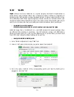
Страница 114: ... matches that of switch port VLAN ID is a 12 bit number PCP Priority Code Point is a 3 bit number and reserved for QoS VLAN IDs range from 2 to 4094 with 0 1 and 4095 reserved for special purposes they are different from switches to switches Our PCP definition comply with IEEE 802 1p protocol ranging from 0 to 7 with 0 as the default value In normal cases you don t need to set PCP value Using the ...

Страница 115: ... properly Figure 5 12 3 Assign VLAN ID to LAG Trunking or LACP 1 After creating LAG press OP button next to the LAG and select Set VLAN ID Figure 5 12 4 2 Put in the VLAN ID and click ok VLAN ID of LAG 0 is properly set Figure 5 12 5 ...

Страница 116: ...N ID You need to repeat step 1 and step 2 to set VLAN ID for the aggregation group Assign VLAN ID to replication port Please consult figure 5 11 3 of 5 11 Replication section for details Always make sure correct VLAN IDs are assigned to the correct network ports iSCSI switch and host NIC to ensure valid connections ...

Страница 117: ...sk slot read block error ERROR HDD write error Disk slot write block error ERROR HDD error Disk slot is disabled ERROR HDD IO timeout Disk slot gets no response INFO PD upgrade started PD string starts upgrading firmware process INFO PD upgrade finished PD string finished upgrading firmware process WARNING PD upgrade failed PD string upgrade firmware failed HW events Level Type Description WARNING...

Страница 118: ...tring is not present ERROR Fan over speed Fan string is over speed WARNING Thermal level 1 System temperature string is higher ERROR Thermal level 2 System Overheated string ERROR Thermal level 2 shutdown System Overheated string The system will auto shutdown immediately ERROR Thermal level 2 CTR shutdown The controller will auto shutdown immediately reason Overheated string WARNING Thermal ignore...

Страница 119: ...deleted to obtain extra snapshot space INFO Snap take A snapshot on VD name has been taken INFO Snap set space Set the snapshot space of VD name to number MB INFO Snap rollback started Snapshot rollback of VD name has been started INFO Snap rollback finished Snapshot rollback of VD name has been finished WARNING Snap quota reached The quota assigned to snapshot name is reached INFO Snap clear spac...

Страница 120: ...hold Exceed Condition occurred for attribute string WARNING SMART fail JBOD name disk slot Failure to get S M A R T information INFO PD dedicated spare Assign JBOD name PD slot to be the dedicated spare disk of RG name INFO PD global spare Assign JBOD name PD slot to Global Spare Disks ERROR Config read fail Config read error occurred at LBA address address of JBOD name PD slot ERROR Config write ...

Страница 121: ...UI INFO System web reboot System reboot from string via Web UI INFO System LCM reboot System reboot via LCM INFO FW upgrade start System firmware upgrade starts INFO FW upgrade success System firmware upgrade succeeds WARNING FW upgrade failure System firmware upgrade is failed ERROR IPC FW upgrade timeout System firmware upgrade timeout on another controller INFO Config imported string config imp...

Страница 122: ... LAN number is enabled for Replication portal INFO Replication portal disabled Replication portal is disabled INFO VD replicate started VD name starts replication process INFO VD replicate finished VD name finished replication process WARNING VD replicate failed The replication in VD name failed INFO VD replicate aborted The replication in VD name was aborted INFO VD set as replica VD name has bee...

Страница 123: ...s 6 2 0 742 0 5 el5 in kernel 2 6 18 Mac ATTO Xtend SAN iSCSI initiator v3 10 System Requirements 1 Mac OS X v10 5 or later For ATTO Xtend SAN iSCSI initiator it is not free Please contact your local distributor GbE iSCSI HBA card Vendor Model HP NC380T PCI Express Gigabit 2 ports TCP IP offload iSCSI offload QLogic QLA4010C PCI X Gigabit 1 port TCP IP offload iSCSI offload QLogic QLA4052C PCI X G...

Страница 124: ...S 2 ST31000640SS 1TB 7200RPM SAS 3 0Gb s 16M F W 0002 Seagate Cheetah NS 2 ST3600002SS 600GB 10000RPM SAS 2 0 6 0Gb s 16M F W 0004 Seagate Cheetah 15K 7 ST3600057SS 600GB 15000RPM SAS 2 0 6 0Gb s 16MB F W 0004 Seagate Constellation ES ST31000424SS 1TB 7200RPM SAS 2 0 6 0Gb s 16MB F W 0005 Seagate Constellation ES ST32000444SS 2TB 7200RPM SAS 2 0 6 0Gb s 16MB F W 0005 SAS 2 5 Vendor Model Seagate S...

Страница 125: ...200RPM SATA 3 0Gb s 32M F W SN06 Seagate SV35 5 ST3500410SV 500GB 7200 RPM SATA 3 0Gb s 16M NCQ F W CV11 Seagate Constellation ES ST31000524NS 1TB 7200RPM SATA 3 0Gb s 32M NCQ F W SN11 Westem Digital Caviar SE WD800JD 80GB 7200RPM SATA 3 0Gb s 8M Westem Digital Caviar SE WD1600JD 160GB 7200RPM SATA 1 5G s 8M Westem Digital Caviar RE2 WD4000YR 400GB 7200RPM SATA 1 5Gb s 16M NCQ Westem Digital Cavia...

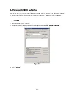
Страница 126: ...oft iSCSI Initiator Please visit Microsoft website for latest iSCSI initiator This example is based on Microsoft Windows Server 2008 R2 Connect 1 Run Microsoft iSCSI Initiator 2 Input IP address or DNS name of the target And then click Quick Connect Figure B 1 3 Click Done ...

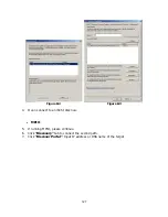
Страница 127: ...re B 2 Figure B 3 4 It can connect to an iSCSI disk now MPIO 5 If running MPIO please continue 6 Click Discovery tab to connect the second path 7 Click Discover Portal Input IP address or DNS name of the target ...

Страница 128: ...128 Figure B 4 Figure B 5 8 Click OK Figure B 6 Figure B 7 ...

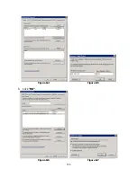
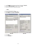
Страница 129: ...nable Enable multi path checkbox Then click OK 11 Done it can connect to an iSCSI disk with MPIO MC S 12 If running MC S please continue 13 Select one target name click Properties 14 Click MCS to add additional connections Figure B 8 Figure B 9 15 Click Add 16 Click Advanced ...

Страница 130: ...130 Figure B 10 Figure B 11 17 Select Initiator IP and Target portal IP and then click OK 18 Click Connect 19 Click OK Figure B 12 Figure B 13 20 Done ...

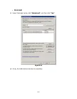
Страница 131: ...131 Disconnect 21 Select the target name click Disconnect and then click Yes Figure B 14 22 Done the iSCSI device disconnect successfully ...

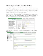
Страница 132: ...HDD trays with either multiplexer board or bridge board to install your HDDs in order to utilize the dual controller mode features Otherwise the IP SAN system will not be able to recognize the HDDs Before you can insert the second controller to the IP SAN storage the IP SAN storage system should be up and running and looks like the following screenshot in Maintenance System Note that the status is...

Страница 133: ...below to upgrade to dual controller mode Step 1 Go to Maintenance System Copy the IP SAN storage serial number Step 2 Go to Maintenance Upgrade and paste the serial number into Controller Mode section Select Dual as operation mode ...

Страница 134: ...134 Step 3 Click confirm The system will ask you to shutdown Please shutdown IP SAN storage Click Ok ...

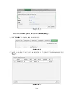
Страница 135: ...DSN 6110 or DSN 6410 Insert the second controller to the IP SAN storage And then power on the system The IP SAN storage should now become in dual controller mode as either DSN 6120 or DSN 6420 You may go to Maintenance System information to check out The IP SAN storage is running in dual controller mode now ...

Отзывы: