


4 Web-based Switch Configuration
D-Link DGS-2000 Series Ethernet Switch User Manual
3
3
9
9
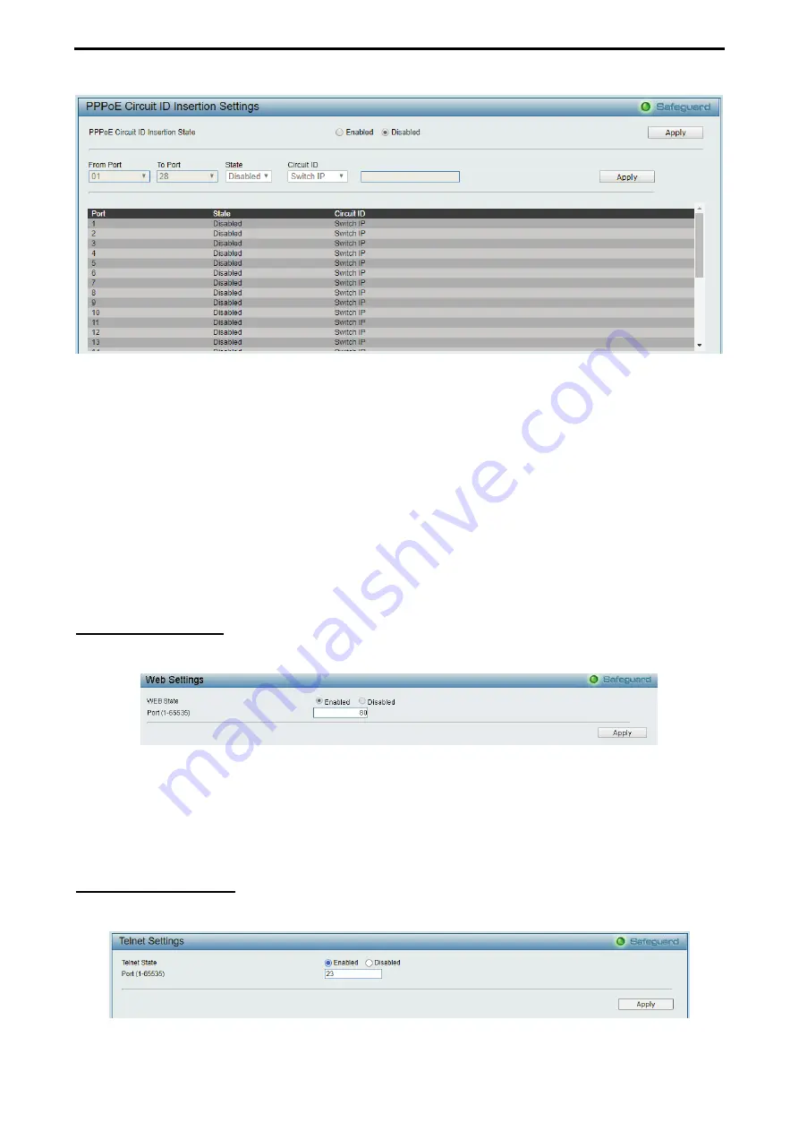
Figure 4.35 – System > PPPoE Circult ID Insertion Settings
PPPoE Circuit ID Insertion State:
Enable or disable the PPPoE circuit insertion state, and Click Apply to
make the configurations take effect.
From Port/ To Port:
Specifies the ports to be configured.
State:
Enable or disable the state of specified ports.
Circuit ID:
Specifies the Circuit ID is
Switch IP
,
Switch MAC, UDF String, Vendor2
and
Vendor3.
Switch IP –
The Switch’s IP address will be used to encode the circuit ID option. This is the default.
Switch MAC –
The MAC address of the Switch will be used to encode the circuit ID option.
UDF String
– A user specified string to be used to encode the circuit ID option. Enter a string with
the maximum length of 32.
Click
Apply
to make the configurations take effect.
System > Web Settings
The WEB State is
Enabled
by default. If user chooses to disable this by selecting Disabled, user will lose the
ability to configure the system through the web interface as soon as these settings are applied.
Figure 4.36 – System > Web Settings
Port (1-65535):
Specifies the Port number. The range is between 1 and 65535 with the well-known default is
80.
Click
Apply
to make the configurations take effect.
System > Telnet Settings
Telnet configuration is
Enabled
by default. If user does not want to allow the Telnet configuration, they only
need to disable the Telnet State.
Figure 4.37 – System > Telnet Settings


