Getting Started with EZ-
PD™ CCG3
Document No. 002-00210 Rev. *A
30
5.4
Re-test CY4531 CCG3 EVK Setup with Modified Configuration and Type-C Power
Adapter
This section describes the steps to observe the behavior when the CY4531 CCG3 EVK with modified configuration
parameters is connected to the Type-C power adapter. The same
section is used in this section as well.
1. Disconnect all connections shown in
, and connect CY4500 EZ-PD Protocol Analyzer to the PC (USB
Host) using a micro-USB cable. Ensure that jumper J4 of the CY4531 CCG3
EVK’s daughter card is set to 2-3
position and its jumper J3 is set to 1-2 position.
2. Connect the Type-C plug of the CY4500 EZ-PD Protocol Analyzer to the Type-C port of the CCG3 EVK.
3. Launch the EZ-PD Analyzer Utility from
Windows
>
All Programs
>
Cypress
>
EZ-PD Analyzer Utility
>
EZ-PD Analyzer Utility
and click on the “
Start Capturing
to start capturing the CC
traffic.
4. Connect the Apple 29W USB-C power adapter to the Type-C receptacle of the CY4500 EZ-PD Protocol Analyzer
). Observe that the PD traffic is being captured on the EZ-PD Analyzer Utility.
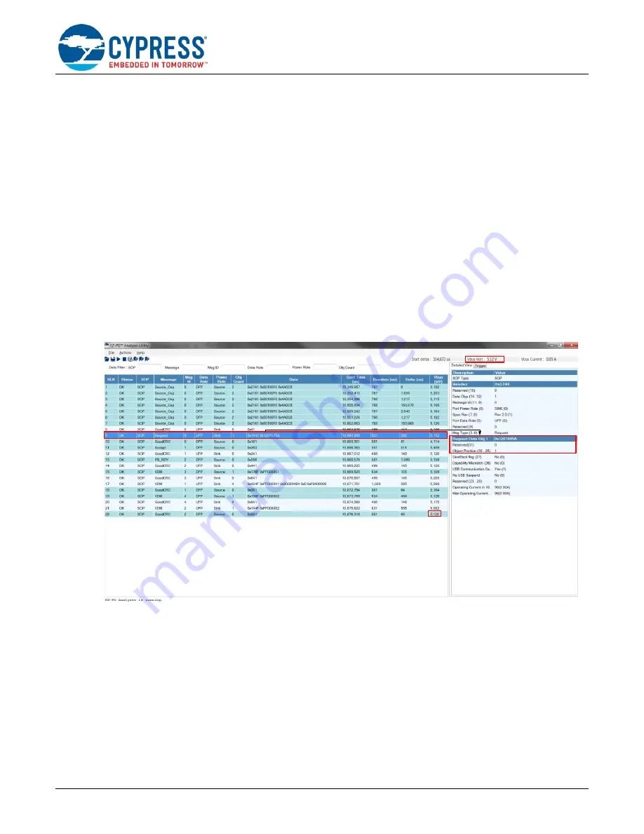
5. From analyzing the CC traffic and looking at the V
BUS
voltage at the end of the captured data as shown in
, it can be seen that a successful PD contract is established at 5V this time with the Type-C power adapter
providing 5V to the Type-C port of the CCG3 EVK.
Figure 28. CC Trace Showing Power Contract Establishment @ 5V with Modified Configuration Parameters
, the CCG3 device requests the source PDO object 1, i.e., source PDO1. This
implies that the custom PDO at 14.8V, 900mA (supported by the Type-C power adapter) is no longer supported
as a sink PDO by the Type-C port of CY4531 CCG3 EVK, because the sink PDOs of the CCG3 device have
been successfully updated.
7. This can also be verified by measuring the voltage on the power output header J7 of the CCG base board using
a multimeter. The output voltage on this header will be about 5V, which is the established power contract
between the two devices. Also, looking at the
, it can be seen that the V
BUS
voltage is
set to 5V at the end of the power contract negotiation.


