background image


HOW TO DETERMINE THE POWER REQUIREMENTS OF YOUR EQUIPMENT 


1. 

Make sure that the total Volt-Amp (VA) requirements of your computer; monitor and peripheral 

equipment does not exceed 1440VA. 

2. 

Insure that the equipment plugged into the three battery power-supplied outlets does not exceed the 

UPS unit’s rated capacity (825VA/410W for CPS825AVR).  If rated unit capacities are exceeded, an 

overload condition may occur and cause the UPS unit to shut down or the circuit breaker to trip. 

3. 

If the power requirements of your equipment are listed in units other than Volt-Amps (VA), convert Watts 

(W) or Amps (A) into VA by doing the calculations below.  Note:  The below equation only calculates the 

maximum amount of VA that the equipment can use, not what is typically used by the equipment at any 

one time.  Users should expect usage requirements to be approximately 60% of below value. 


TO ESTIMATE POWER REQUIREMENTS: 


      Watts (W) x 2.0 =          VA or        Amps (A) x 120 =       VA 

Add the totals up for all pieces of equipment and multiply this total by .6 to calculate actual requirements There 

are many factors that can affect the amount of power that your computer system will require.  The total load that 

you will be placing on the battery-powered outlets should not exceed 80% of the unit’s capacity. 


INSPECTION 


The box should contain the following: 

(1) PowerPanel Plus™ software (floppy disk); (1) serial interface cable (DB-9); (1) serial to USB adapter cable; (1) 

telephone communication cable; (1) user manual; (1) warranty registration card; (1) UPS unit. 


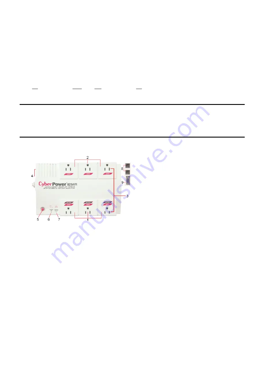
DESCRIPTION 


5.  Power Switch 

Can be used as the master on/off switch for 
computer equipment connected to the battery 
power supplied outlets. 

6.  Power On Indicator 

This LED is illuminated when the utility condition 
is normal and the UPS outlets are providing


“clean” 

power, free of surges and spikes.  

7.  

Electrical Wiring Fault Indicator 

This LED indicator will illuminate to warn the user 
that a wiring problem exists 

with the AC outlet

.  

If this LED is illuminated, user is advised to 
unplug all electrical equipment from the outlet 
and have an electrician check the outlet to insure 
proper wiring. 

8.  Communication Protection Ports 

Communication protection ports will protect any 
standard modem, fax, or telephone line. 

9.  Serial Port to PC 
This port allows connection and 

communication from the DB-9 serial or USB port 
on the computer to the UPS unit.  The UPS 
communicates its status to the PowerPanel 
Plus™ software.  This interface is also 
compatible with the UPS service provided by 

Windows NT, Windows 2000 and Windows XP.

1.  

Battery Backup and Surge Protection Outlets

Provides three battery-supplied outlets with 
Automatic Voltage Regulation for consistent output 
power to connected equipment. 

2.


 “Always-On” Surge Protection Outlets 

Provides three surge-protected outlets to protect 
connected equipment against surges and spikes. 

3.  All outlets Designed for AC Adapters 

Allows six AC power adapter blocks to be plugged 
into the UPS without making adjacent outlets 
inaccessible. 

4.  Resettable Circuit Breaker 

Located on the side of the UPS, the circuit breaker 
provides circuit overload and fault protection.  
Under normal operating conditions, the circuit 
breaker is depressed. 

Содержание CPS825AVR

Страница 1: ...User Manual for CPS825AVR with USB Interface and PowerPanel Plus Software ADDITIONAL INSTALLATION TIPS CAN BE FOUND AT www cyberpowersystems com faqs htm...

Страница 2: ...source before servicing the battery or installing a computer component DO NOT USE FOR MEDICAL OR LIFE SUPPORT EQUIPMENT CyberPower Systems does not sell products for life support or medical applicatio...

Страница 3: ...ard 1 UPS unit DESCRIPTION 5 Power Switch Can be used as the master on off switch for computer equipment connected to the battery power supplied outlets 6 Power On Indicator This LED is illuminated wh...

Страница 4: ...ephone icon can be used to protect a telephone or fax machine line 5 Plug the UPS into a properly grounded wall outlet Make sure the wall outlet is protected by a fuse or circuit breaker and does not...

Страница 5: ...e will appear on your screen for a few seconds and then minimize It will appear as a blue and white battery icon located in the system tray near the clock FOR WINDOWS NT 1 Click on Start point to Sett...

Страница 6: ...o an AC outlet turn the UPS on and then start your computer 8 Windows will find New Hardware 9 Insert the PowerPanel Plus primary disk into the floppy drive 10 Follow the on screen instructions 11 Onc...

Страница 7: ...n your computer system on It can only be set when a Scheduled Off is also set Scheduled On settings that are set to occur within seven days will be displayed When the UPS is in standby after the Sched...

Страница 8: ...ault Click this button to return the software to original factory settings 9 Cancel This button exits the window without saving changes 10 OK This button exits the window and saves changes 11 UPS Comm...

Страница 9: ...will display the names and location of any files that were auto saved by the software TESTING YOUR UPS SYSTEM Once you have set up your UPS system you may wish to test it Make sure that the UPS has b...

Страница 10: ...armful to skin and eyes and may be toxic CAUTION A battery can present a high risk of short circuit current and electrical shock Take the following precautions before replacing the battery 1 Remove al...

Страница 11: ...REMINDER Batteries are consider HAZARDOUS WASTE and must be disposed properly Contact your local government for more information about proper disposal and recycling of batteries...

Страница 12: ...Beep Overload Occurs in the Battery power Supplied Outlets Turn the UPS off and unplug at least one piece of equipment from the UPS Wait 5 seconds reset the circuit breaker and turn the UPS on Off Off...

Страница 13: ...the computer for an additional serial port Move the cable to this port The unit is not providing battery power Shutdown your computer and turn the UPS off Wait 10 seconds and turn the UPS back on This...

Страница 14: ...erage under the Limited Warranty and the Power Control Guarantee Registration is not required for Limited Warranty coverage but note if you do not complete a registration card you will be required to...

Страница 15: ...mple a sales receipt that establishes you as the Initial Customer the original consumer purchaser of the Product within ten 10 days of the event for which you want to make a claim for warranty service...

Страница 16: ...volt power lines in the United States and Canada transients surges or spikes on standard telephone land lines PBX telephone equipment lines or Base 10 100T Ethernet lines when properly installed and c...

Страница 17: ...pment into an outlet on a circuit different from that to which the receiver is connected 4 Consult the dealer or an experienced radio TV technician for help Any special accessories needed for complian...

Отзывы: