Installation
V.34bis Series Standalone & Rackmount Modems
9
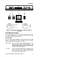
Determining the optimum location is the combination of several factors and
compromises. For the desktop installation it is a matter of operator
convenience and effectiveness, and the modem's proximity to line power, to
the telephone wall jack, to the telephone set (if it is to be used with the
modem) and to the location of the terminal equipment.
The rackmount chassis is typically located in a cabinet/rack that holds other
equipment or other rackmount chassis of modems. Adequate line power for
all the equipment in the cabinet must be available or brought to the chosen
location. The modem printed circuit assemblies (cards) require about 15
inches in front of the cabinet to be plugged in and out of the rackmount
chassis. Since an operator is expected to walk in front of the cabinet to
operate and observe the front panel on some occasions the space for
passage should at least be the 15 inches needed for the modem.
The rackmount modems and their chassis are designed with free airflow in
the vertical direction to provide natural convection cooling. The
specifications for the modems require a maximum ambient temperature for
the modem card of 122
°
degrees F. The modem rackmount chassis may
be stacked and the air will flow through the stack, but the considerations of
the temperature and the flow of the air become more critical. When
rackmount modem chassis are located in cabinets with other equipment
that would block the convection cooling it is necessary to provide a
minimum of one and one-half inches of unobstructed space at the top and
bottom so that airflow is not restricted. When the heat generated by the
equipment in the cabinet cannot be ventilated by convection cooling then
forced airflow is required. This may be done by the addition of a blower
assembly to the cabinet to force air through the equipment. In a computer
room there may be cooled air moving through ducts that may be vented into
the cabinet by only providing the appropriate openings in the floor.
Telephone Line Access
The proximity to the telephone lines must be considered in the planning
phase of the installation. The consideration of routing dial lines from a
corporate PBX system may be involved and require consultation with the
group that maintains the PBX system. The routing of bundles of cables and
the consideration of the 50 pin connector termination or the use of multiple
RJ-45 type jacks requires analysis. The future expansion or changing
requirements of the data communication system may become a part of this
decision. The use of digital lines has many of the same considerations, but
it is more likely that the Bell Operating Company serving your facility must
be consulted for determining the location for the line installation effort and
the type of connections that are the most reasonable for now and in the
future. The schedule for the planned telephone line installation may
become a critical part of completing the installation in a timely manner.
System Start-Up
Содержание V.34bis series
Страница 10: ...Introduction 6 V 34bis Series Standalone Rackmount Modems ...
Страница 22: ...Installation 18 V 34bis Series Standalone Rackmount Modems ...
Страница 40: ...Modes and Configurations 36 V 34bis Series Standalone Rackmount Modems ...
Страница 52: ...Modes and Configurations 48 V 34bis Series Standalone Rackmount Modems AT Z0 Tom XXZYY N store Tom ...
Страница 65: ...Modes and Configurations V 34bis Series Standalone Rackmount Modems 61 ...
Страница 118: ...AT and V 25bis Command Sets 114 V 34bis Series Standalone Rackmount Modems ...
Страница 128: ...S Registers 124 V 34bis Series Standalone Rackmount Modems ...
Страница 150: ...Index 146 V 34bis Series Standalone Rackmount Modems ...


