Chapter 5 Console Operation
35
5.2 Set E1 card
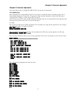
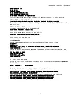
Press 1 from the main menu to configure the E1 card. If no E1 card is found, the display shows:
NO E1 CARD
If the types of two E1 cards are inconsistent, the display shows:
INPUT E1 LINE(1-8):1
Press number key 1 to 8 to enter a corresponding sub menu of E1 channel.
Press 0 or ESC to return to the upper menu.
Once selected, the E1 card will be checked, the configuration displayed, and current status of E1 card shown.
E1-1 current parameter:
LINE:CCS,CRC4 DISABLE,NOLOOP,HDB3,RECEIVE JITTA
NMP:NMP DISABLE,0
BERT:BERT DISABLE,2E11-1,NONE
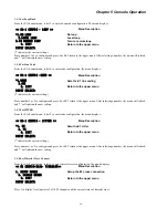
E1 channel menu display
<< E1-1 CONFIG >>
Menu Description
1. E1 FRAME/TS0 PASS
Set frame mode and timeslot 0 bypass
2. E1 CRC
Set CRC-4 mode
3. E1 LOOP
Set loop back test mode
4. CODE
Set E1 line code
5. JITTER
Set E1 JITTER
6. TIMESLOT CROSS
Set timeslot cross connections
0. EXIT
Return to the upper menu
INPUT SELECT:
Press number key 1 to 6 to enter the corresponding sub menu.
Press 0 or ESC return to the upper menu.
5.2.1 Set Frame Mode
From the E1 channel menu, select 1 to enter frame mode configuration. The menu displays:
<< E1-1 CONFIG - FRAME/TS0 >>
Menu Description
*1. CCS(31 SLOTS)
Sets the E1 framing
2. CAS (30 SLOTS)
3. CCS TS0 PASS(31 SLOTS)
(
CCS+TimeSlot0 Pass
)
4. CAS TS0 PASS(30 SLOTS)
(
CAS+ TimeSlot0 Pass
)
0. EXIT
Return to the upper menu
INPUT SELECT:
('*' indicates the current setting.)
Press number 1 to 4 to configure and press 0 or ESC return to the upper menu. After selecting a number, the menu will refresh,
and '*' will indicate the new setting.
5.2.2 Set CRC Mode
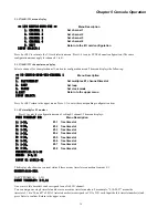
From the E1 channel menu, select 2 to enter CRC mode configuration. The menu displays:
<< E1-1 CONFIG - CRC4 >>
Menu Description
1.CRC4 ENABLE
With CRC check
*2.CRC4 DISABLE
No CRC check
0. EXIT
Return to the upper menu
INPUT SELECT:
('*' indicates the current setting.)
Press number 1 to 2 to configure and press 0 or ESC return to the upper menu. After selecting a number, the menu will refresh,
and '*' will indicate the new setting.
Содержание ERM-MUX
Страница 1: ...ERM MUX Plus E1 Multi Service Access Multiplexer ...
Страница 2: ......
Страница 8: ...Table of Contents ...
Страница 20: ...Chapter 2 Installation 20 This page was left blank intentionally ...
Страница 30: ...Chapter 3 LED Indicators and Cable Pin Definitions 30 This page was left blank intentionally ...
Страница 58: ...Chapter 8 Application Notes 58 This page was left blank intentionally ...
Страница 59: ......
Страница 60: ......


