Chapter 1 Introduction
9
Chapter 1 Introduction
The ERM-MUX/PLUS Time Division-Multiplexer supports eight E1 channels that provide the functions of multiplexing and
cross-connection of data/voice/CAS-signaling. The MUX is designed for multiplexing Nx64Kbps, 64K/128Kbps, 9.6Kbps
synchronous data, asynchronous data below 19.2Kbps , G703/64K data and voice signals into 2.048Mbps ITU-T G.703 E1
frames. The cross-connecting function includes the intercrossing of CAS-signaling.
The types and quantity of subscriber's data and voice interface modules can be flexibly selected according to needs. The
modules can be plugged into any interface slots according to specific maintenance and application methods. All time slots may
be user defined. If more ports are required than are allotted by the main chassis, an extension chassis may be connected later as
required.
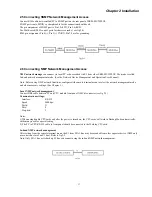
The ERM-MUX/PLUS supports SNMP (Under development) and/or NMP GUI network management with local PC or via a
dedicated timeslot from the E1 line. The NMP GUI can manage more ERM-MUX/PLUS equipment via the E1 network in-line
or in nested structures. A console terminal mode is supported as well. When SNMP management mode is available and
selected, remote Telnet and HTTP embedded web server are also available for management.
The ERM-MUX/PLUS supports complete redundant functions for the electrical input service, the power module cards, CPU
card and E1 card. The E1 backup provides 1+1 modes. All of these cards are capable of automatic switchover in case of failure.
The system has complete warning and diagnostic functions for stable and reliable operation.
Power supply options for 110V AC, 220V AC or -48V DC, ensure maximum flexibility for central office installations.
This equipment complies fully with all ITU-T standards for E1 transmissions.
1.1 General Features
Structure
19 or 23 inch rack mountable, 4U standard 18-slot chassis, from left to right:
The 1st and 2nd: POWERA slots.
The 3rd and 4th: POWERB slots.
The 5th :CPUA slot.
The 6th :CPUB slot.
The 7th :E1A slot.
The 8th :E1B slot.
The 9th to 18th slots, defined as I/O slot 01 ~ I/O slot
Notice: Each slot has a mark in the front top of the case.
The10th slot, may be used for plugging in any of the following user data interface modules. The position, type, and number
may be selected as required. Any channel of each module can be multiplexed into any one of the eight E1 interfaces, with
timeslots configured at user discretion (either in sequence or non-consecutively).
Cable connectors
Front panel
The I/O of each card is accessed from the front panel connectors.
Backplane
Provided with alarm terminals, connects to rack alarm circuits and under failure conditions, alarm signals are sent from
shelves/racks.
SNMP
SNMP Gateway interface provides 100Base-TX unshielded twisted pair interface. (Under development)
External Clock
G.703 external clock interface provides two types of interfaces, balanced (RJ-45) and unbalanced (BNC) connectors.
Cascade
RS-485 interface is used for cascading expansion rack, and are provided by RJ-45 x 2 connectors.
DB62 connector for connecting backplane data to expansion rack.
Содержание ERM-MUX
Страница 1: ...ERM MUX Plus E1 Multi Service Access Multiplexer ...
Страница 2: ......
Страница 8: ...Table of Contents ...
Страница 20: ...Chapter 2 Installation 20 This page was left blank intentionally ...
Страница 30: ...Chapter 3 LED Indicators and Cable Pin Definitions 30 This page was left blank intentionally ...
Страница 58: ...Chapter 8 Application Notes 58 This page was left blank intentionally ...
Страница 59: ......
Страница 60: ......


