Chapter 4 Hardware Settings
31
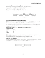
Chapter 4 Hardware Settings
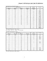
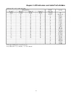
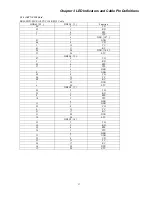
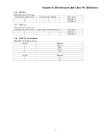
When setting the ERM-MUX/PLUS via NMP management system or Terminal console process, the setting parameters are
stored in non-volatile RAM. In addition to the soft settings, some PCB cards require some settings of DIP switches or jumpers.
4.1 E1 Card
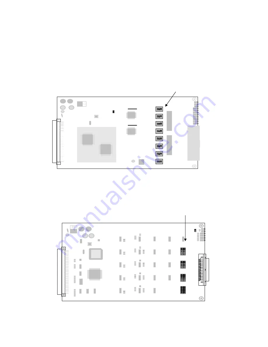
SW2: All "ON" places E1 card interface impedance at 75 ohm for BNC.
All "OFF" places E1 card interface impedance at 120 ohm for RJ-45
4.1 E1 Card
4.2 N64K/V35 Card
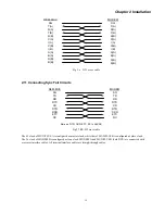
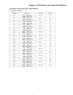
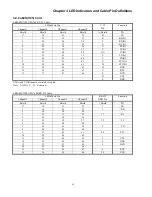
Interface selection
CH1 Jumper: SW7, SW15, SW3, SW11, SW19
CH2 Jumper: SW5, SW13, SW1, SW9, SW7
CH3 Jumper: SW6, SW14, SW2, SW10, SW18
CH4 Jumper: SW8, SW16, SW4, SW12, SW20
When jumpers set on the RS530 side, the channel works as RS530, X.21, or RS449.
When jumpers set on the V35 side, the channel works as V35.
4.2 N64 Card
EMP_8E1- V1.1
6
8
7
5
6
8
7
5
6
8
7
5
6
8
7
5
6
8
7
5
6
8
7
5
6
8
7
5
6
8
7
5
EMP_8E1- SUB_V1.1
SW2
SW2
SW2
SW2
SW2
SW2
SW2
SW2
DIP
Jumpers
R S 5 3 0 V .3 5
R S 5 3 0 V .3 5
R S 5 3 0 V .3 5
R S 5 3 0 V .3 5
M U X _ N 6 4 (V 3 5 )_ V 1 .0
Содержание ERM-MUX
Страница 1: ...ERM MUX Plus E1 Multi Service Access Multiplexer ...
Страница 2: ......
Страница 8: ...Table of Contents ...
Страница 20: ...Chapter 2 Installation 20 This page was left blank intentionally ...
Страница 30: ...Chapter 3 LED Indicators and Cable Pin Definitions 30 This page was left blank intentionally ...
Страница 58: ...Chapter 8 Application Notes 58 This page was left blank intentionally ...
Страница 59: ......
Страница 60: ......

