background image

Chapter 2 Installation


18 

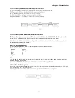
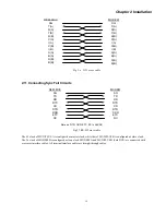
REM-MUX

MODEM

SG

TD(A)

RD(A)

RTS

CD

ETC(B)

RC(B)

SG

TD(A)

RD(A)

RTS

CD

ETC(A)

RC(A)

TD(B)

RD(B)

TD(B)

RD(B)

ETC(A)

RC(A)

ETC(B)

RC(B)


2.7 Connecting Monitor/Control Terminal 

Connect a DB9 to DB9 cable between the PC COM port and CPU card's front panel LOC Ctrl connecter. 
Connect a crossover or null-modem DB9 to DB9 cable between the modem and CPU card's front panel LOC Ctrl connector. 

Communication settings: 

Interface: RS-232 
Speed:  

9600bps/ 

Parity:  

Bits:  

Stop bits: 


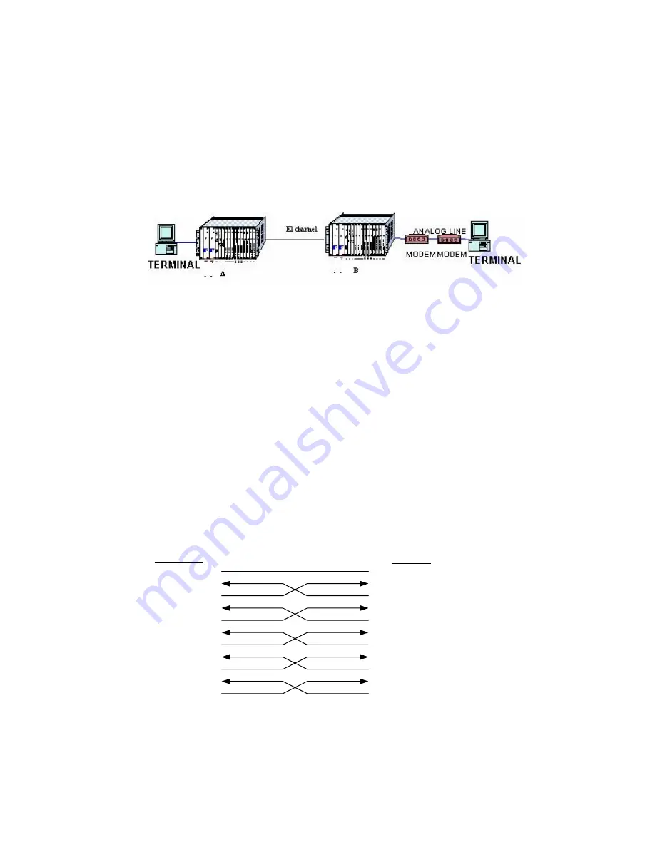
Fig. 2.6 Local and remote management terminal connections 


2.8 Connecting G.703 External Clock   

Unbalance BNC connecter on backplane (EXT CLK)   
Balanced RJ-45 connecter on backplane (EXT CLK), Pin assignments: Pin 4,5 Receive, 7,8 Ground.   
 

2.9 Connecting E1 Circuits 

Connect a DB37 to Unbalance (75ohm) BNC or Balanced (120ohm) RJ-45 connecters cable to the DB37 provided on the front 
panel of the E1 card.   
The RJ-45 follows USOC RJ-48C standard: Pin1,2 Receive, 4,5 Send, 7,8 Ground.   
 
Note: 

1) When using E1 Backup mode, the E1 cable can randomly connect to either E1A or E1B card on the front panel.   
2) When using a single E1, use the E1A slot card.   


2.10 Connecting I/O Cards 

For details of all the different IO cards and their connections from front panel with different cables, see chapter 3.   
The IO cards all have DCE interface. To emulate DTE you must use crossover cables. For DTE crossed cable connection 
methods see fig 2.5 fig 2.9 fig 2.6.   


Fig2.5  V.35 cross cable 

Содержание ERM-MUX

Страница 1: ...ERM MUX Plus E1 Multi Service Access Multiplexer ...

Страница 2: ......

Страница 3: ...h claim alleges that CTC Union Technologies was negligent regarding the design or manufacture of said product TRADEMARKS Microsoft is a registered trademark of Microsoft Corp HyperTerminal is a registered trademark of Hilgraeve Inc WARNING This equipment has been tested and found to comply with the limits for a Class A digital device pursuant to Part 15 of the FCC Rules These limits are designed t...

Страница 4: ...te Version 4 2 March 2011 Update This manual supports the following models ERM MUX Plus This document is the current official release manual Please check CTC Union s website for any updated manual or contact us by E mail at info ctcu com Please address any comments for improving this manual or to point out omissions or errors to marketing ctcu com Thank you 2008 2011 CTC Union Technologies Co Ltd ...

Страница 5: ...14 1 2 10 X 50 Module Line Card 14 1 2 11 SUB E1 Line Card Under Development 14 1 2 12 Power Modules 14 1 2 13 Physical Specifications 14 CHAPTER 2 INSTALLATION 15 2 1 INSTALLING BRACKETS ON CHASSIS 15 2 2 POWER MODULES AND LINE CARD INSTALLATION 15 2 2 1 Cable connectors 16 2 3 AUXILIARY CONNECTIONS ON REAR OF CHASSIS 16 2 4 CONNECTING POWER SUPPLIES 16 2 5 CONNECTING SNMP NETWORK MANAGEMENT ACCE...

Страница 6: ...CARD 39 5 5 SET G703 64K CARD 39 5 5 1 G703 64K menu display 40 5 6 SET A SYNC 128K CARD 40 5 6 1 A SYNC RS232 menu display 40 5 6 2 A SYNC RS232 Channel menu display 40 5 7 SET FXS CARD 41 5 7 1 FXS menu display 41 5 7 2 Channel menu display 41 5 7 3 Set Work mode 41 5 8 SET FXO CARD 42 5 9 SET E M CARD 42 5 9 1 E M MENU DISPLAY 42 5 9 2 E M Channel menu display 42 5 10 SET X 50 CARD 43 5 11 SET ...

Страница 7: ...NG STATUS 52 CHAPTER 6 TEST AND DIAGNOSTICS 53 6 1 E1 LOCAL LOOP 53 6 2 E1 TO REMOTE LOOP 53 6 3 LOOPBACK TEST FOR N64K V35 A SYNC 128K CARD 54 6 4 LOOP TEST FOR G703 64K CARD 54 CHAPTER 7 CLOCK SYNCHRONIZATION 55 7 1 SETTING CLOCK FOR WHOLE MACHINE 55 7 1 1 E1A1 8 s Recover clock 55 7 1 2 Internal clock 55 7 1 3 I O card clock 55 7 1 4 G703 external clock 55 7 2 CONNECTION BETWEEN MULTIPLEXER AND...

Страница 8: ...Table of Contents ...

Страница 9: ... of these cards are capable of automatic switchover in case of failure The system has complete warning and diagnostic functions for stable and reliable operation Power supply options for 110V AC 220V AC or 48V DC ensure maximum flexibility for central office installations This equipment complies fully with all ITU T standards for E1 transmissions 1 1 General Features Structure 19 or 23 inch rack m...

Страница 10: ...ndows NMP GUI E1 network connected to SNMP NMP GUI Local terminal console mode 1 1 3 E1 Line Card E1A and E1B slots can insert two E1 line modules that automatically work in redundant operation or separately Each slot can be selected as 2 4 8 xE1 module When all E1 s are selected as single 1xE1 the 4 E1 channels all support data voice CAS signaling cross connection and multiplexing Notice two E1 m...

Страница 11: ...rts performance monitoring and BERT test through NMP or Terminal console according RFC 1406 recommendation b System supports CRC 4 and BPV monitoring CURR ES UAS LONG ES UAS c System supports Loopback test and BERT test display Rx error amounts Error counts and Bit error rate d System provides test patterns 2e9 1 2e11 1 and 2e15 1 e System provides Error Insertions and rates Single 10e 1 10e 2 10e...

Страница 12: ...may be multiplexed into any of the E1A1 E1A2 E1B1 or E1B2 interfaces For special applications requiring the need for Timeslot 0 to be able to transmit the data of CAS signaling the SUB E1 supports Timeslot 0 bypass 1 1 14 Additional Features Optional expansion chassis for dense data ports application All modules are hot swappable Note The 9th 18th slots are defined as I O slots and described logic...

Страница 13: ...nes E line M line SB battery and SG ground lines Loop current 5 30 mA maximum 70 mA E M Signaling TYPE1 TYPE5 mode independently per port see section 4 3 Voice Transmission technical index LEDs E M signaling status active status or idle status Audio line Impedance 600 ohm Voice attenuation set independently in 0 5dB steps see section 4 3 Wire mode set independently as 2W or 4W by the switch see se...

Страница 14: ...e 128K Bit Error Rate Less than 10 10 Connector 4 pin terminal block x 6 Duplex Full Half 1 2 10 X 50 Module Line Card Multiplexes low speed data onto a single 64Kbps timeslot Standard compliance ITU T X 50 Division 3 with 6 2 packetization Data rates Sync Async 19 2K Data interface V 24 RS 232 1 2 11 SUB E1 Line Card Under Development Specification same as E1 module Description SUB E1 Line Card s...

Страница 15: ... work in hot standby mode capable of automatic switchover if one module fails CPU slots CPUA CPUB are for CPU Cards Both CPU Cards work with one active and one in hot standby mode capable of automatic switchover if one card fails E1 slots E1A E1B are for E1 Line Cards Both E1 Cards work with one active and one in hot standby mode capable of automatic switchover if one card fails IO slots IO slot 0...

Страница 16: ...ectors HDB 62 interface for connecting the expansion chassis bus 2 3 Auxiliary Connections on Rear of Chassis Fig 2 3 ERM MUX PLUS Backplane 2 x AC POWER shown 2 4 Connecting Power Supplies User can select 110VAC 220VAC or DC power modules AC and DC backplane are different AC AC model is shown in figure 2 3 The connecter for alarm relays can be connected to the existing alarm system When the Major...

Страница 17: ... NMP network functions configure with console terminal menu to select the network management mode and other necessary settings See Chapter 5 Local NMP network management Connect DB9 cable between PC and CPU module front panel NM Ctrl connecter see fig 2 5 Communication settings Interface RS 232 Speed 9600bps Parity N Bits 8 Stop bits 1 Notes 1 When using double CPU cards and after the power is tur...

Страница 18: ... EXT CLK Balanced RJ 45 connecter on backplane EXT CLK Pin assignments Pin 4 5 Receive 7 8 Ground 2 9 Connecting E1 Circuits Connect a DB37 to Unbalance 75ohm BNC or Balanced 120ohm RJ 45 connecters cable to the DB37 provided on the front panel of the E1 card The RJ 45 follows USOC RJ 48C standard Pin1 2 Receive 4 5 Send 7 8 Ground Note 1 When using E1 Backup mode the E1 cable can randomly connect...

Страница 19: ...cross cable The E1 clock of MUX PLUS A is configured as master clock while that of MUX PLUS B is configured as slave clock The Tx clock of MODEM B is configured as loop clock MODEM A and MUX PLUS B both DCE are connected with crossover interface cables All terminal interface cables are straight through cables REM MUX MODEM SG TD RD RTS CD DTR DSR ETC RC SG TD RD RTS CD DTR DSR ETC RC Note no DTR D...

Страница 20: ...Chapter 2 Installation 20 This page was left blank intentionally ...

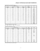
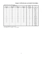
Страница 21: ...en lit indicates SYNC Loss Signal Loss when off normal when lit indicates SYNC Loss Signal Loss when off normal when lit indicates SYNC Loss Signal Loss when off normal when lit indicates SYNC Loss Signal Loss when off normal G703 64K Card PWR Alarm Ch1 Ch2 Ch3 Ch4 green red red red red red when lit indicates Card power normal when off Card power fault when lit indicates Card alarm when off normal...

Страница 22: ...h5 Ch6 green red green green green green green green when lit indicates Card power normal when off power fault when lit indicates Card alarm when off normal lit when Signaling is active lit when Signaling is active lit when Signaling is active lit when Signaling is active lit when Signaling is active lit when Signaling is active FXO Card PWR Alarm Ch1 Ch2 Ch3 Ch4 Ch5 Ch6 green red green green gree...

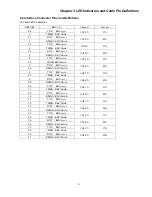
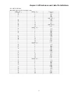
Страница 23: ...e 25 TRING BNC Shield CH3 TX TX3 7 RTIP BNC core 26 RRING BNC Shield CH3 RX RX3 8 TTIP BNC core 27 TRING BNC Shield CH4 TX TX4 9 RTIP BNC core 28 RRING BNC Shield CH4 RX RX4 29 TTIP BNC core 11 TRING BNC Shield CH5 TX TX5 30 RTIP BNC core 12 RRING BNC Shield CH5 RX RX5 31 TTIP BNC core 13 TRING BNC Shield CH6 TX TX6 32 RTIP BNC core 14 RRING BNC Shield CH6 RX RX6 15 TTIP BNC core 34 TRING BNC Shie...

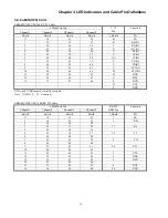
Страница 24: ...9 27 43 61 U ETC A 10 28 44 62 W ETC B 11 29 45 63 H DTR 15 33 49 67 C RTS 13 31 47 65 F DCD D CTS E DSR XX A and XX B must be twisted wire pair Note V35PIN F D E shorted ERM MUX PLUS N 64K RS 232 Cable 68Pin Male Pin Channel 1 Channel 2 Channel 3 Channel 4 RS 232 DB25 Pin Function Shield Shield Shield Shield 1 Shield PG 17 18 51 52 7 SG 1 19 35 53 3 RD 2 20 36 54 3 21 37 55 17 RC 4 22 38 56 5 23 ...

Страница 25: ...B 13 31 47 65 8 DCD A 14 32 48 66 10 DCD B 15 33 49 67 4 RTS A 16 34 50 68 19 RTS B 5 CTS A 13 CTS B 6 DSR A 22 DSR B XX A and XX B must be twisted wire pair Note DB25 PIN 8 5 6 shorted 10 13 22 shorted ERM MUX PLUS N 64K X 21 Cable 68Pin Male Pin Channel 1 Channel 2 Channel 3 Channel 4 X 21 DB15 Pin Function Shield Shield Shield Shield 1 Shield PG 17 18 51 52 8 SG 1 19 35 53 4 R A 2 20 36 54 11 R...

Страница 26: ... 1 19 35 53 6 RD A 2 20 36 54 24 RD B 3 21 37 55 8 RC A 4 22 38 56 26 RC B 5 23 39 57 5 TC A 6 24 40 58 23 TC B 7 25 41 59 4 TD A 8 26 42 60 22 TD B 9 27 43 61 17 ETC A 10 28 44 62 35 ETC B 11 29 45 63 12 DTR A 12 30 46 64 30 DTR B 13 31 47 65 13 DCD A 14 32 48 66 31 DCD B 15 33 49 67 7 RTS A 16 34 50 68 25 RTS B 11 DSR A 29 DSR B 9 CTS A 27 CTS B XX A and XX B must be twisted wire pair Note DB37 ...

Страница 27: ... DSR 107 43 7 GND 46 8 CD 2 15 TC 45 17 RC 24 20 DTR 108 23 24 ETC DB25 F 2 47 2 TD 5 3 RD 25 4 RTS 27 5 CTS 6 DSR 4 7 GND 49 8 CD 26 15 TC 48 17 RC 7 20 DTR 6 24 ETC DB25 F 3 50 2 TD 29 3 RD 8 4 RTS 10 5 CTS 6 DSR 11 7 GND 52 8 CD 9 15 TC 51 17 RC 31 20 DTR 30 24 ETC DB25 F 4 53 2 TD 12 3 RD 32 4 RTS 34 5 CTS 6 DSR 35 7 GND 55 8 CD 33 15 TC 54 17 RC 14 20 DTR 13 24 ETC ...

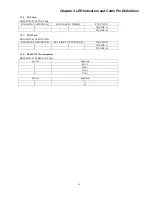
Страница 28: ...4 ETC DB25 F 6 59 2 TD 19 3 RD 39 4 RTS 41 5 CTS 6 DSR 42 7 GND 61 8 CD 40 15 TC 60 17 RC 21 20 DTR 20 24 ETC 3 2 4 G703 64K Card ERM MUX PLUS G703 64K Cable RJ 45 Function 1 RTIP 2 RRING 3 TTIP 4 TRING 7 GND 8 GND 3 2 5 E M Card ERM MUX PLUS E M Cable RJ 45 Definition 1 4W send 2W LINE A 2 4W send 2W LINE B 3 4W receive 2W LINE A 4 4W receive 2W LINE B 5 E LINE Signaling 6 M LINE Signaling 7 SG 8...

Страница 29: ...K TO MUXPLUS RJ11 LINK TO PHONE FUNCTION 4 2 2W LINE A 5 3 2W LINE B 3 2 7 FXO Card ERM MUX PLUS FXO Cable RJ45 LINK TO MUXPLUS RJ11 LINK TO EXCHANGE FUNCTION 4 2 2W LINE A 5 3 2W LINE B 3 2 8 RS485 422 Pin Assignment ERM MUX PLUSRS485 422 Port 4 wires Function 1 RX 2 RX 3 TX 4 TX 2 wires Function 1 2 ...

Страница 30: ...Chapter 3 LED Indicators and Cable Pin Definitions 30 This page was left blank intentionally ...

Страница 31: ...s E1 card interface impedance at 120 ohm for RJ 45 4 1 E1 Card 4 2 N64K V35 Card Interface selection CH1 Jumper SW7 SW15 SW3 SW11 SW19 CH2 Jumper SW5 SW13 SW1 SW9 SW7 CH3 Jumper SW6 SW14 SW2 SW10 SW18 CH4 Jumper SW8 SW16 SW4 SW12 SW20 When jumpers set on the RS530 side the channel works as RS530 X 21 or RS449 When jumpers set on the V35 side the channel works as V35 4 2 N64 Card EMP_8E1 V1 1 6 8 7...

Страница 32: ...e B means connected to B side C means not connected Jumper setting Jumper TYPE 1 TYPE 2 TYPE 3 TYPE 4 TYPE 5 S1 B B B A A S2 C A A B C S3 A B A B A S4 B B B A A S5 B B B A A Table 4 1 5 kind of Signaling Type S1 S5 setting 1SA1 1SA5 2W 4W 2SA1 2SA5 3SA1 3SA5 CH1 CH2 CH3 A CH4 CH2 CH3 CH1 RJ45X6 SSA1 SSA 3 4SA1 4SA5 CH4 CH5 CH6 Pin 1 Fig 4 2 E M card Pin 8 CH1 CH2 CH3 CH4 CH5 CH6 top bottom 5SA1 5S...

Страница 33: ...s been set up load the parameters saved in computer and configure the system The terminal will display INIT WAIT SYSTEM PARAMETER SAVE OK The system will search for each card and set up with current parameters If there are no current parameters omit this step INITIALIZING PLEASE WAIT Then it searches each module and sets system by current parameters if there are no current parameters this item won...

Страница 34: ...M NET MANAGER 5 1 2 Input Password Under console monitor operations such as modifying parameters can be done only after inputting password at the prompt The system displays PLEASE INPUT PASSWORD The password must be six characters and can contain any letter or number You can try again if the wrong password is input The default factory password is 111111 no quotes The system will show for each char...

Страница 35: ...per menu INPUT SELECT Press number key 1 to 6 to enter the corresponding sub menu Press 0 or ESC return to the upper menu 5 2 1 Set Frame Mode From the E1 channel menu select 1 to enter frame mode configuration The menu displays E1 1 CONFIG FRAME TS0 Menu Description 1 CCS 31 SLOTS Sets the E1 framing 2 CAS 30 SLOTS 3 CCS TS0 PASS 31 SLOTS CCS TimeSlot0 Pass 4 CAS TS0 PASS 30 SLOTS CAS TimeSlot0 P...

Страница 36: ...etting Press number 1 or 2 to configure and press 0 or ESC return to the upper menu After selecting a number the menu will refresh and will indicate the new setting 5 2 5 Set JITTER From the E1 channel menu select 5 to enter code configuration the menu displays E1 1 CONFIG JITTER Menu Description 1 RX Setu the E1 Jitter 2 TX 0 EXIT Return to the upper menu INPUT SELECT indicates the current settin...

Страница 37: ...ay shows the slot number for each I O card IO CONFIG SEARCH BOARD NO 1 2 3 4 5 6 If there are no I O cards NULL be displayed INPUT BOARD NO Input the slot number to enter the corresponding configuration menu for that card If the selected slot is empty then the warning message will display THE NO BOARD IS EXIT INPUT PLEASE AGAIN BOARD NO 1 2 3 4 5 6 INPUT BOARD NO 5 3 1 N64K V35 card configuration ...

Страница 38: ...pper menu Press 1 3 to enter the corresponding configuration item 5 3 4 Set multiplex E1 number Press 1 to enter the configuration menu of setting E1 channel The menu displays The display also shows any current status if there are any timeslots connection from any E1 CURRENT E1A1 NULL INPUT EXAMPLE 3 9 11 INPUT TIMESLOT 3 9 11 One or more idle timeslots can be assigned to one N64 I O channel You c...

Страница 39: ...ays I O CONFIG N64 V35 CHANNEL 1 CLOCK Menu Description 1 INTERNAL Set internal clock 2 EXTERNAL Set external clock 0 EXIT Return to the upper menu INPUT SELECT 0 indicates the current setting Press 1 or 2 to select the clock mode configuration Press 0 or ESC to return to the upper menu After keying 1 or 2 the menu will be shown again and will indicate the new setting 5 4 Set RS 232 Card Please re...

Страница 40: ...ARK RD DTR OFF RTS OFF CH5 NULL INTERNAL CLOCK NORMAL MARK TD MARK RD DTR OFF RTS OFF CH6 NULL INTERNAL CLOCK NORMAL MARK TD MARK RD DTR OFF RTS OFF 5 6 1 A SYNC RS232 menu display I O CONFIG A SYNC 128K Menu Description 1 CHANNEL 1 Set channel 1 2 CHANNEL 2 Set channel 2 3 CHANNEL 3 Set channel 3 4 CHANNEL 4 Set channel 4 5 CHANNEL 5 Set channel 5 6 CHANNEL 6 Set channel 6 0 EXIT Return to the in...

Страница 41: ... O card sub menu Press 1 to 6 to enter the FXS channel configuration The setting procedure is the same for each channel 1 6 5 7 2 Channel menu display When selecting one FXS channel for example CH1 the menu displays IO CONFIG FXS CHANNEL 1 Menu Description 1 E1 TIMESLOT Set multiplex E1 channel 2 WORK MODE Set work mode 0 EXIT Return to the upper menu INPUT SELECT Press 0 or ESC return to the uppe...

Страница 42: ...ORMAL 0 0db 0 0db 5 9 1 E M MENU DISPLAY I O CONFIG E M Menu Description 1 CHANNEL 1 Set channel 1 2 CHANNEL 2 Set channel 2 3 CHANNEL 3 Set channel 3 4 CHANNEL 4 Set channel 4 5 CHANNEL 5 Set channel 5 6 CHANNEL 6 Set channel 1 0 EXIT Return to the main menu of IO card INPUT SELECT Press 0 or ESC to return to the I O card sub menu Press 1 to 6 to enter the E M channel configuration The setting pr...

Страница 43: ...CONFIG ET100 CHANNEL 1 1 E1 TIMESLOT 2 AUTO NEGOT 3 COMMUNICATION MODE 4 SPEED 5 FLOW CONTROL 6 MAC FILTERING 7 LOCAL LOOP 0 EXIT INPUT SELECT Press 0 or ESC return to the upper menu Press 1 7 to enter the corresponding configuration sub menu 5 11 1 Set multiplex E1 number Press 1 to display the configuration menu of setting E1 channel The menu displays Select E1 line 1 8 Press 0 or ESC return to ...

Страница 44: ...NFIG ET100 CHANNEL 1 SPEED 1 100M 2 10M 0 EXIT INPUT SELECT 5 11 5 Set Flow Control Press 5 to display the configuration menu of setting Flow Control The menu displays INPUT SELECT 5 I O CONFIG ET100 CHANNEL 1 FLOW CONTROL 1 DISABLE 2 ENABLE 0 EXIT INPUT SELECT 5 11 6 Set MAC FILTERING Press 6 to display the configuration menu of setting MAC FILTERING The menu displays INPUT SELECT 6 I O CONFIG ET...

Страница 45: ... CONFIG RS485 1 CHANNEL 1 2 CHANNEL 2 3 CHANNEL 3 4 CHANNEL 4 5 CHANNEL 5 6 CHANNEL 6 0 EXIT INPUT SELECT Press 0 or ESC return to the I O configuration sub menu Press 1 6 to enter the RS485 channels configuration 5 12 2 RS485 Channel Configuration Display When entering the RS485 card configuration under the RS485 channel configuration sub menu CHANNEL ONE FOR EXAMPLE the system checks and display...

Страница 46: ...ain menu INPUT SELECT 1 Pressing 1 will show the following status Presence of cards Working status Configuration parameters Note The system will not automatically refresh when in 3 DISPLAY CONFIG only in the main menu 2 4 5 Press 2 to display the working status of each plug in module including CPU power fan E1 and I O cards The system will refresh in real time It will also display the status of G ...

Страница 47: ...configuration success or failure C B BOARD SET OK E1A 8 E1 BOARD SET OK E1B 8 E1 BOARD SET OK slot 1 N64 V35 BOARD SET OK slot 2 A SYNC 128K BOARD SET OK slot 3 E M BOARD SET OK slot 4 FXO BOARD SET OK slot 5 G703 64K BOARD SET OK slot 6 FXS BOARD SET OK 5 15 Reset Device Configuration to Default After pressing 5 from the main menu the system asks to recover to default YOU WILL RECOVER SYSTEM TO D...

Страница 48: ...LOT slot 01 N64K V35 slot 05 G703 slot 10 N64K 232 CURRENT IO CLOCK SLOT NULL The listed cards are all candidates for providing clock source If entering 5 the system will show INPUT SLOT NO 5 Note Only the clock from the first channel CH1 of the selected slot can be used to apply clock for the whole system when the I O card clock is used 5 17 Modify NMP SNMP Parameter Please press 3 to enter 3 NMP...

Страница 49: ...000000 INPUT NEW COMMUNITY RD WR N CURRENT COMMUNITY RD ONLY 00000000 INPUT NEW COMMUNITY RD ONLY Public CURRENT COMMUNITY RD ONLY Public CURRENT ACCESS IP ADDR 1 000 000 000 000 INPUT NEW ACCESS IP ADDR 1 192 168 10 4 CURRENT ACCESS IP ADDR 1 192 168 010 004 CURRENT ACCESS IP ADDR 2 000 000 000 000 INPUT NEW ACCESS IP ADDR 2 192 168 10 5 CURRENT ACCESS IP ADDR 2 192 168 010 005 CURRENT ACCESS IP ...

Страница 50: ...DEVICE ADDRESS ADDRESS 1 2 ADDRESS 2 0 ADDRESS 3 0 ADDRESS 5 1 INPUT 2nd DOWN DEVICE ADDRESS ADDRESS 1 2 ADDRESS 2 0 ADDRESS 3 0 ADDRESS 5 64 NEW DOWN DEVICE ADDRESS 2 0 0 1 2 0 0 64 5 18 SET BACKUP E1 Please press 4 to enter 4 BACKUP E1 The menu will display SYSTEM CONFIG BACKUP E1 Menu Description 1 DISABLE 2 ENABLE 0 EXIT Return to the upper menu INPUT SELECT 1 Press 0 or ESC return to the main...

Страница 51: ... BERT test channel INPUT E1 LINE 1 8 2 5 22 1 Set BERT Test In the BERT test menu press 1 to choose modify and set BERT test item and the menu displays BERT TEST FUNCTION Menu Description 1 STOP Stop BERT test 2 OFFLINE offline test 3 ONLINE Online test 0 EXIT Return to previous menu INPUT SELECT 1 indicates current setting Press 1 3 to choose setting press 0 Enter or ESC to return to upper menu P...

Страница 52: ...ut the position of is changed with the setting value 5 22 4 Display BERT Test Result In BERT test menu press 5 to display BERT test result the menu displays BERT RESULT E1 2 PERFERMANCE Bipolar violations count BPV 0 Current CRC 4 error count 0 Current errored seconds ES 0 Current unavailable seconds UAS 0 Current seconds SEC 0 Long term errored seconds LES 0 Long term unavailable seconds LUAS 0 L...

Страница 53: ...e is disconnected from external E1 line see figure 6 1 then looped back from TX This aims to test the device at the user side Connect a bit error rate tester such as CTC Union s HCT 6000 BERT to any user data port to check error rate 6 2 E1 To Remote Loop Figure 6 2 To Remote Loop Near the external side of E1 the TX and RX are connected to form a To Remote Loop see figure 6 2 which is used to test...

Страница 54: ... cards The tested loop is bi directional and two BERTs should be working fine 6 4 Loop Test for G703 64K Card Fig 6 5 G 703 64K Loopback Figure 6 5 shows the schematic diagram for loop test for G703 64K card The tested loop is a unidirectional loop TX HCT BERT TD RD N64K V35 RS232 RX E1 Board E1 Board N64K V35 RS232 HCT BERT TD RD local remote Tx HCT BERT G703 64K Board Rx E1 Board ...

Страница 55: ...ternal clock and so the G 703 external clock is the system source 7 2 Connection between multiplexer and synchronous terminal device In the following examples the clock setting methods are described Figure 7 1 The direct connection between multiplexer and synchronization terminal device Both of MUX PLUS A and B can adopt recovery clock or one recovery clock and other internal clock All terminal de...

Страница 56: ...ts In the figure 8 3 user data No 1 to No 6 can be in one time slot or a group of time slots The network in figure 8 3 shows User data 1 is transmitted from Site A to B user data 2 transmitted from Site A to Site C user data 3 transmitted from Site A to Site D user data 4 transmitted from Site B to Site C user data 5 transmitted from Site B to Site D user data 6 transmitted from Site C to Site D Y...

Страница 57: ...LUS via FXS card and multiplex it to corresponding time slot of E1A2 and E1B2 3 For E1 circuits of both sides E1A1 is connected to E1B1 and E1B2 is connected to E1A2 A makes communication with A and B makes communication with B 8 6 Typical application of G703 64K card In the figure 8 6 Signal from G703 64K card is sent to opposite side via E1 line and then sent to ERM MUX PLUS from the opposite si...

Страница 58: ...Chapter 8 Application Notes 58 This page was left blank intentionally ...

Страница 59: ......

Страница 60: ......

Отзывы: