Chapter 5 Console Operation
39
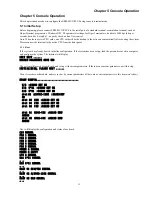
If the input timeslot has already been assigned previously, the system will prompt:
Press 0 or ESC return to the upper menu. Press 1-8 to enter the E1 configuration item
THE TIMESLOT ALREADY USED!
INPUT AGAIN!
INPUT TIMESLOT:
If no timeslot number has been input, then press Enter or ESC to return to the upper menu.
5.3.5 Set loop mode
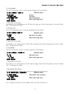
Press 4 to set loop mode of I/O channel. The menu displays
<< IO CONFIG-N64K-V35-CHANNEL 1-LOOPBACK >>
Menu Description
*1. NORMAL
Without loop
2. LOCAL LOOP
3. REMOTE LOOP
4. LOOP
0. EXIT
Return to the upper menu
INPUT SELECT:0
('*'indicates the current setting.)
Press 1 - 4 to select the loop back configuration. Press 0 or ESC to return to the upper menu. After key 1 -4 is pressed, the
menu will be shown again, and '*' will indicate the new setting.
5.3.6 Set clock mode
Press 6 to set the clock mode of the I/O channel. The menu displays
<< I/O CONFIG-N64/V35-CHANNEL 1-CLOCK >>
Menu Description
*1. INTERNAL
Set internal clock
2. EXTERNAL
Set external clock
0. EXIT
Return to the upper menu
INPUT SELECT:0
('*'indicates the current setting.)
Press 1 or 2 to select the clock mode configuration. Press 0 or ESC to return to the upper menu. After keying 1 or 2, the menu
will be shown again, and '*' will indicate the new setting.
5.4 Set RS-232 Card
Please refer to N64K/V35 configuration settings which are applied the same way to RS-232 card.
5.5 Set G703-64K Card
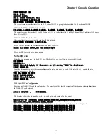
When entering the G703-64K card configuration under the I/O card sub-menu, the display will show the current configuration
and status information of the G703-64K card selected.
slot 5 G703-64K STAT:NORMAL
Slot number card type card status
CH1:NOE1:NULL,INTERNAL CLOCK,NOLOOP,NORMAL,SIGNAL LOSS
The display shows the status of each channel, including multiplexed E1 channel, timeslot, clock mode, loop mode.
CH2:NOE1:NULL,INTERNAL CLOCK,NOLOOP,NORMAL,SIGNAL LOSS
CH3:NOE1:NULL,INTERNAL CLOCK,NOLOOP,NORMAL,SIGNAL LOSS
CH4:NOE1:NULL,INTERNAL CLOCK,NOLOOP,NORMAL,SIGNAL LOSS
Содержание ERM-MUX
Страница 1: ...ERM MUX Plus E1 Multi Service Access Multiplexer ...
Страница 2: ......
Страница 8: ...Table of Contents ...
Страница 20: ...Chapter 2 Installation 20 This page was left blank intentionally ...
Страница 30: ...Chapter 3 LED Indicators and Cable Pin Definitions 30 This page was left blank intentionally ...
Страница 58: ...Chapter 8 Application Notes 58 This page was left blank intentionally ...
Страница 59: ......
Страница 60: ......

