Vortex FP Compact Installation & Operation Manual
10
Issue 1, January 2013
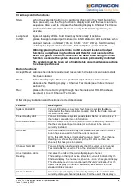
Channel Test mode, see section 7.4 of the standard Vortex manual.
Channel Alarm 1 and Alarm
2 LEDs
Red LEDs for each channel. Illuminated when the alarm level is
reached on the channel. When the alarm is first raised, the LED
flashes. After the ACCEPT/RESET button is pressed, the LED goes
out if the alarm condition has been cleared. If the alarm condition still
exists, it displays continuously.
Channel Fault LEDs
Yellow LED for each channel. Illuminated when a fault is detected on
the channel. When the fault is first raised, the LED flashes. After the
ACCEPT/RESET button is pressed, the LED goes out if the fault has
been cleared. If the fault still exists, it displays continuously.
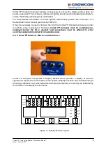
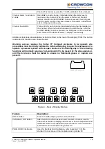
Additional functions are available via buttons fitted to the rear of the display PCB. The button
locations and functions are shown below.
Warning: access requires the Vortex FP Compact enclosure to be opened; site
procedures must be strictly adhered to before attempting to open the enclosure or to
operate a powered system with an open enclosure. Performing any of the following
functions will normally require a ‘hot-work permit’ to be issued by the site supervisor,
and the local area must be tested to ensure no flammable gases or vapours are
present.
ACCEPT/RE
RUN
HOLD
ZERO
CAL
PEAKHOLD
CH TEST
STEP
LAMP TEST
INHIB1
INHIB2
INHIB3
RIBBON CABLE CONNECTOR
Figure 4 – Rear of Display Module
Feature
Description
HOLD Button
Press to hold the display on the current channel.
CHANNEL TEST Button
After the HOLD button has been used to select a channel, use the
Channel Test button to display alarm levels or for zero adjustment and
calibration. Refer to the standard Vortex manual for more information.
This button can be disabled using Vortex PC.
PEAK HOLD CAL Button
Used for the Peak Hold Calibration, refer to section 7.3 of the
standard Vortex manual. Can be disabled using Vortex PC.


