background image

Vortex FP Compact Installation & Operation Manual

4

Issue 1, January 2013

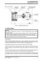
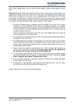
Figure 1 – System Base-Plate View

2. INSTALLATION

General Notes

:

Vortex FP Compact weighs approximately 37.5Kg. Appropriate lifting equipment must be
used when transporting and mounting the system.The surface to which the system will be
mounted, and the fixings used must be able to support its weight adequately.

Care should be taken so as to avoid damage the painted finish of the system.

Vortex FP Compact has an ingress protection rating of IP66 and is therefore suitable for
outdoor installation. It is recommended however that a suitable sun-shade and rain canopy
is fitted.

Cabling must be in accordance with the recognised standards of the appropriate authority in
the country concerned and meet the electrical requirements of the field devices.

Field cables must be connected to the system using ATEX certified Exd cable glands, which
are suitable for the type of cable used. Crowcon recommends Steel Wire Armoured (SWA)

Warning

This product is designed for use in Zone 1, Zone 2 hazardous areas, and is certified
ATEX Ex d IIB+H

2

.

Installation must be in accordance with the stipulations made on the ATEX certificate,
and the recognised standards of the appropriate authority in the country concerned.
For further information please contact Crowcon. Prior to carrying out any installation work
ensure local regulations and site procedures are followed.

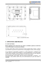
AC

mains

Terminals

Node Controller Module

Quad Input
Module(s)

Relay Output
Module(s)

DC Power Distribution
Terminals Modules

Power
Supply Unit

Содержание Vortex FP Compact

Страница 1: ...Vortex FP Compact Flameproof Gas Detection Control System Installation and Operation Manual Issue 1 January 2013...

Страница 2: ...described in this instruction manual has mains voltages applied to it Ensure correct safety procedures are adopted before working on the equipment The equipment described in this manual is designed f...

Страница 3: ...TENTS 1 INTRODUCTION 3 1 1 SAFETY INFORMATION 3 1 2 PRODUCT DESCRIPTION 3 2 INSTALLATION 4 3 OPERATION MAINTENANCE 6 3 1 APPLYING POWER 6 3 2 COMMISSIONING 7 3 3 ROUTINE MAINTENANCE 7 3 4 VORTEX FP CO...

Страница 4: ...ated control system designed for monitoring up to twelve gas detectors Three input channels may alternatively be used for monitoring conventional smoke or heat detectors or flame detectors Vortex FP C...

Страница 5: ...the recognised standards of the appropriate authority in the country concerned and meet the electrical requirements of the field devices Field cables must be connected to the system using ATEX certifi...

Страница 6: ...s Once the brackets are attached close the door and restrain using one fixing bolt before attempting to mount the cabinet 2 Lift the system in to place and secure via the mounting bracket fixing point...

Страница 7: ...cted to the fused terminal A wiring diagram is shown on the next page If the equipment is permanently connected to a mains supply then a dedicated circuit breaker must be included in the installation...

Страница 8: ...tallations are fully commissioned as soon as possible after installation Commissioning should include a full check of cabling and equipment functions as well as output functions Gas detectors must be...

Страница 9: ...functions Vortex FP Compact must be completely de energised before the lid is opened local procedures must be adhered to when servicing equipment installed in a hazardous area 3 4 VORTEX FP COMPACT D...

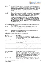
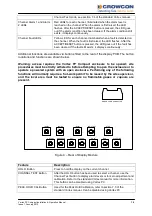
Страница 10: ...art cycling through the channels after HOLD has been selected or to end Channel Test mode Other display indications and functions are described below Feature Description System Fault LED Yellow LED in...

Страница 11: ...ctions are shown below Warning access requires the Vortex FP Compact enclosure to be opened site procedures must be strictly adhered to before attempting to open the enclosure or to operate a powered...

Страница 12: ...ftware can be used to inhibit individual channels Note Even in the inhibit condition the alarm LEDs on the display module are triggered if alarms occur 4 TECHNICAL SPECIFICATION Size 450mm x 330mm x 2...

Страница 13: ...ter packaging of the returned goods Units returned to Crowcon as faulty and are subsequently found to be fault free or requiring service may be subject to a handling and carriage charge Warranty Discl...

Страница 14: ...salesusa crowcon com Website www crowcon us European Office Crowcon Detection Instruments Ltd Vlambloem 129 3068JG Rotterdam Netherlands Tel 31 10 421 1232 Fax 31 10 421 0542 Email eu crowcon com Web...

Отзывы: