Vortex FP Compact Installation & Operation Manual
11
Issue 1, January 2013
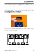
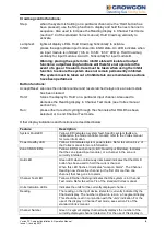
CAL Button
Used for the Calibration, refer to sections 3.8 and 7.3 of the standard
Vortex manual. Can be disabled using Vortex PC.
ZERO Button
Used for the Zero Adjustment refer to sections 3.8 and 7.3 of the
standard Vortex manual. Can be disabled using Vortex PC.
ZONE INHIBIT Buttons
One button for each zone (Quad Input Module). Used to prevent the
corresponding output relays from being activated during testing or
calibration. Refer to sections 3.8, 7.3 and 7.4 of the standard Vortex
manual. Vortex PC software can be used to inhibit individual
channels.
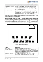
Note: Even in the inhibit condition, the alarm LEDs on the display
module are triggered if alarms occur.
4. TECHNICAL SPECIFICATION
Size:
450mm x 330mm x 289mm (width x height x depth)
Construction:
LM25 alloy, polyester powder coated
Weight:
37.5Kgs approx.
Cable entries:
10 x M20
Certification:
ATEX Ex II 2G
Exd IIB+H
2
T5
Inputs:
Refer to the specification sheet provided with the
system.
Outputs:
Refer to the specification sheet provided with the
system.
Power supply:
85 - 264Vac 50-60Hz, 0.8A max.
20-30Vdc, 5A
Internal PSU:
24Vdc, 2.5A nominal (4.4A max)
Operating Temperature:
-10 to +40º C (storage temperature -25 to +55ºC)
Humidity:
15-90% non-condensing
Ingress Protection
IP66
CE Approvals
Low Voltage Directive EN61010-1:2010
EMC EN50270: 2006


