

1592039020 XLH210 GB r1.0 Gas Leak Detector 2016.04.26.doc
XLH210
1/2
GAS
LEAK
DETECTOR
XLH210
1.
GENERAL WARNINGS
1.1
PLEASE READ BEFORE USING THIS MANUAL
•
This manual is part of the product and should be kept near the instrument for easy and quick reference.
•
The instrument shall not be used for purposes different from those described hereunder. It cannot be
used as a safety device.
•
Check the application limits before proceeding.
•
Dixell Srl reserves the right to change the composition of its products, even without notice, ensuring the
same and unchanged functionality.
1.2
SAFETY PRECAUTIONS
•
Check the supply voltage is correct before connecting the instrument.
•
Do not expose to water or moisture: use the controller only within the operating limits avoiding sudden
temperature changes with high atmospheric humidity to prevent formation of condensation
•
Warning: disconnect all electrical connections before any kind of maintenance.
•
Fit the sensor where it is not accessible by the End User. The instrument must not be opened.
•
In case of failure or faulty operation send the instrument back to the distributor or to “Dixell S.r.l.” (see
address) with a detailed description of the fault.
•
Consider the maximum current which can be applied to each relay (see Technical Data).
•
Ensure that the wires for sensor, loads and the power supply are separated and far enough from each
other, without crossing or intertwining.
•
In case of applications in industrial environments, the use of mains filters (our mod. FT1) in parallel with
inductive loads could be useful.
•
This unit must be installed by a suitably qualified technician who will install this unit in accordance with
these instructions and the standards in their particular industry/country. Operator of the unit should be
aware of the regulations and standards in their industry/country for the operation of this unit. These notes
are only intended as a guide and the manufacturer bears no responsibility for the installation or operation
of this unit.
2.
GENERAL DESCRIPTION
The XLH210 is a microprocessor controller suitable for for 4÷20mA gas sensors.
The alarm thresholds can be set with display visualization and recognized through Pre-Alarm and Alarm relay.
It has an RS485 serial output with RTU Modbus protocol to monitor remotely the XWEB monitoring system.
3.
INSTALLATION AND MOUNTING
87
230
M
AX
3
7
21
0
130
12
0
M
A
X
2
8
H
I
Fig. 1
3.1
WALL MOUNTING
1.
Unscrew the 2 screws that keep connected the frontal and lower parts and separate the 2 parts
2.
Unscrew the 4 frontal screws and remove the cover
3.
Make the proper holes for cable-presses or pipe-presses using the centres signed in the bottom cover
(Fig. 1, H, I)
4.
Make 3 holes in the wall, as indicated in Fig. 1 to fix the controller
5.
Fix the cable-presses and the pipe-presses
6.
Insert the wall-nugs, contained in the kit, into the holes made in the wall. Then use the o-rings and fix
the back part of the controllers by means of the 3 screws to the wall itself
7.
Insert the wiring cables in cable-presses or in the pipe-presses
8.
Mount the frontal part using the previous 4 screws; do not press excessively in order to avoid plastic
deformation
9.
After connecting the wires to the terminal blocks close the cover (Fig. 2, c) and fix it by the screws
4.
DIMENSIONS
210
87
23
0
5.
GAS LEAK DETECTOR CONNECTIONS
The instruments are provided with screw terminal block to connect cables with a cross section up to 2,5 mm
2
.
Heat-resistant cables have to be used. Before connecting cables make sure the power supply complies with the
instrument’s requirements. Separate the sensor cables from the power supply cables, outputs and the power
connections. Do not exceed the maximum current allowed on each relay, in case of heavier loads use a
suitable external relay.
5.1
GAS SENSOR CONNECTIONS
For the functioning of the sensor, please refer to the manual provided by the manufacturer.
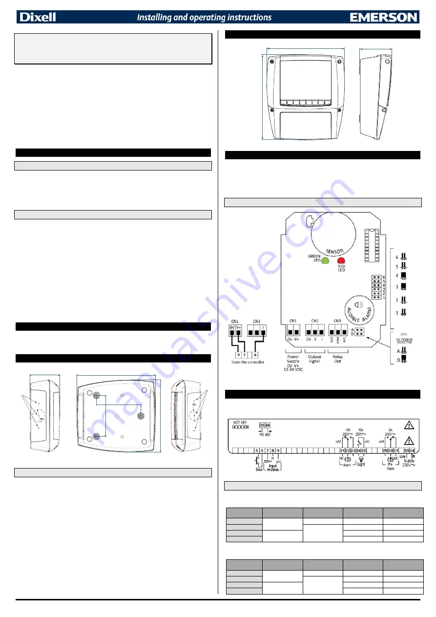
6.
XLH210 CONNECTIONS
6.1
RELAY AND BUZZER STATUS DURING THE ALARM
Note: this is the relay output situation with the parameter AS=oP.
STATUS
ALARM RELAY
OUTPUT
PRE-ALARM
RELAY OUTPUT
LABEL ON THE
DISPLAY
BUZZER
ON (no alarm)
22-23
29-30
ON
OFF
Pre-Alarm
30-31
PAL
INTERMITTENT
ALARM
21-22
ALL
CONTINUOS
OFF
OFF
OFF
Note: this is the relay output situation with the parameter AS=cL.
STATUS
ALARM RELAY
OUTPUT
PRE-ALARM
RELAY OUTPUT
LABEL ON THE
DISPLAY
BUZZER
ON (no alarm)
21-22
30-31
ON
OFF
Pre-Alarm
29-30
PAL
INTERMITTENT
ALARM
22-23
ALL
CONTINUOS
OFF
OFF
OFF


