


Installation 6
Butt connectors with plastic insulators - For
wire sizes AWG 14, 12 and 10 (2, 3, and
5.5mm²):
1. Cut off motor leads. Stagger lead and wire
length so that 2nd lead is 4” (100mm) longer
than 1st lead and 3rd lead is 4” (100mm)
longer than second.
2. Cut off cable ends. Be sure to match colors
and lengths of wires in drop cable to colors
and lengths of motor leads.
3. Trim insulation back 1/2” (13mm) from cable
ends and motor lead ends.
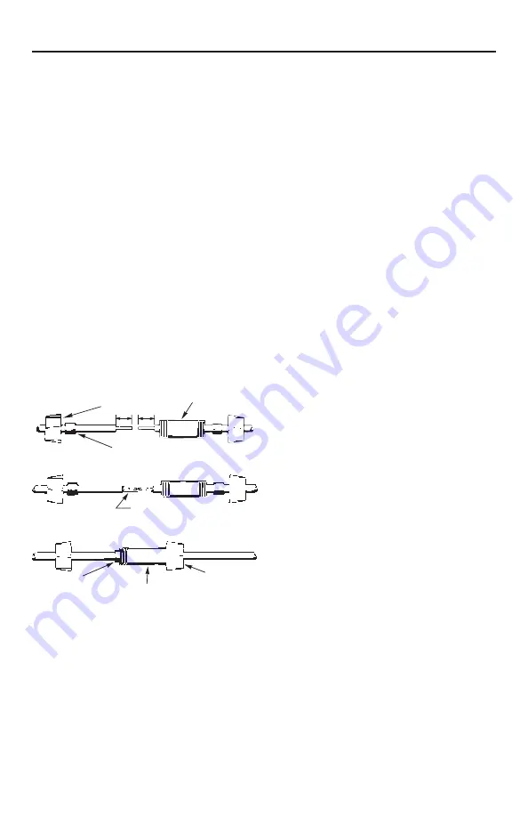
4. Unscrew plastic caps from insulators. Place a
cap and a neoprene gasket sleeve on each wire
end to be spliced (see Figure 7).
5. Slide insulator body onto one wire end
(Figure 7).
6. Insert wire end into butt connector and crimp
(see Figure 8). Be sure to match cable and
motor wire colors.
7. Center insulator body over splice and slide
neoprene sleeves into body as far as they
will go. Screw caps onto insulator body
(Figure 9) and tighten by hand for a strong,
waterproof splice.
Po wer Supply Cable Installation
1. To test submersible pump, momentarily
connect it to proper power supply. Power
supply frequency and voltage must match
motor nameplate frequency and voltage to
within ±10%.
2. Fasten cable leads securely to pump discharge
section; leave 4-5” (100-127mm) of slack in
leads at this point. Securely fasten leads to
plastic pipe within 6” (150mm) of the pump
discharge section. Use properly-installed
torque arresters to protect pump and pipe from
twisting damage as pump starts and stops.
3. A copper ground wire at least as large as
wires supplying current to the motor must
be connected in designated location. Most
submersible motors will include a ground
lead for connection. Other motors will have
designated location on motor bracket.
4. Use only submersible cable supplied by pump
manufacturer. When lowering pump into well,
secure cable to discharge pipe at 10’ (3.5m)
intervals with electrical tape. Take care not to
damage pump cable.
NOTICE To avoid dropping the pump down
the well or damaging cable or cable splices,
NEVER allow pump cable to support weight
of pump.
Pump Installation
1. If a standard air over water pressure tank is
being used, install two bleeder orifices about
2’ (60cm) apart as shown in Figure 11. These
orifices will automatically charge the tank with
air. See Figure 11 to determine orifice location.
NOTICE If a pre-charged tank is used, DO
NOT install bleeder orifices. If pump and
pre-charged tank are replacing a standard
tank system, remove bleeder orifices before
installing pump in well.
2. To prevent losing pump down the well,
connect a safety rope strong enough to support
pump and drop pipe (minimum 5/16” [8mm]
twisted polypropylene or synthetic manila
rope) through eyelet, around pump discharge.
Tie off other end of safety rope securely to well
seal, well cap or pitless adapter.
3. Discharge outlet is 1-1/4” NPT threaded.
Use 100 PSI (689.5kPa) rated polyethylene
plastic pipe for installations up to
100’ (30.5M) depth.
Use 160 PSI (1103.2 kPa) rated
polyethylene plastic for installations up to
220’ (67.1M) depth.
For depths beyond 220’ (67.1M) use
galvanized steel pipe for the entire drop pipe.
Insulator body centered over splice
Gasket sleeve in place
Cap screwed on
Butt connector or
crimp or solder
6469 1111
End cap
Gasket
Insulator body
1/2”
(12.7mm)
Figure 7
Figure 8
Figure 9
Содержание 102890199
Страница 24: ......


