Coulomb Technologies ChargePoint CT2025 Скачать руководство пользователя страница 37

Installing the head assembly and access panel

4-3

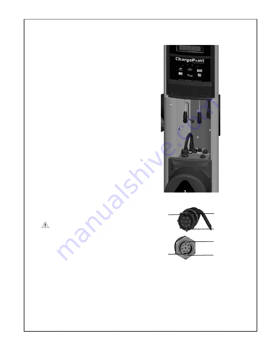
Step 2 - Install head assembly

To install the head assembly:

• Remove the plastic wrap from the 

face of the head assembly and retain 
the affixed provisioning label for 
future use (see page 4-11).

• Insert the head assembly into the 

main body’s access panel opening, 
then slide it into the body far enough 
to connect the wiring.

• Connector the blue circular connector 

(without the Ground wire) to the blue 
connector on the terminal block, as 
illustrated.

• Connect the head assembly’s 

rectangular connector to the 
receptacle on the right side of the 
terminal block, ensuring it is fully 
seated.

• Connect the circular connector 

containing the Ground wire to the 
cable assembly, then connect its 
Ground wire to the vacant Ground tab 
on the cable assembly.

• Keeping cables out of the way (by 

pushing them to the back and side), 
firmly slide the head assembly all the 
way into body. 

IMPORTANT: 

Ensure that the 

head assembly is fully seated and 
that no gap exists between the 
bottom of the head assembly and the 
top of the cable assembly. The head 
assembly fits tightly and may require 
extra downward force to ensure it is 
fully seated.

• If the head assembly is not fully 

seated, visually verify that the cable 
assemblies and the black filler panel 
are fully seated. If necessary, press 
down on the head assembly to seat 
the gaskets.

Using the white arrow as a guide, align the circular 
connector so that:
• the key slot in the connector matches up with the 

key in the receptacle AND

• the tabs on the connector match up with the tab 

slots on the receptacle

Insert the connector until fully seated (do not use 
excessive force).

Rotate connector’s outer ring in a clockwise direction 
until snug.

Tab #1

Semi-circular 
groove (or 
“key slot)” in 
connector

Semi-circul
ar key in 
receptacle

Tab #2

Tab slot #2

Tab slot #1

Содержание ChargePoint CT2025

Страница 1: ...arging Station Installation Guide Part Number 75 001082 01 Revision 5 0 Coulomb Technologies Inc 1692 Dell Ave Campbell CA 95008 6901 USA US toll free 1 877 370 3802 www coulombtech com www mychargepo...

Страница 2: ...oulomb and its distributors expressly disclaim all implied warranties including any warranty of design merchantability fitness for a particular purposes and non infringement to the maximum extent perm...

Страница 3: ...2 Attach holsters to body assembly 3 3 Step 3 Route the RF cables under the top front panel 3 4 Step 4 Install cable assembly 2 3 5 Step 5 Install filler panel 3 7 Step 6 Install cable assembly 1 3 8...

Страница 4: ...ding error messages 6 2 Troubleshooting the light 6 6 Resolving a Relay Stuck Open fault 6 7 Checking voltages 6 8 APPENDICES A Prepare Installation Site Bollard Mount Before you start A 1 Installing...

Страница 5: ...Charging Stations Data Sheet available at www coulombtech com library php review the mounting template provided in this document and in the box containing the station s body IMPORTANT A PDF version o...

Страница 6: ...Fault Detection 20 mA CCID with auto retry 15 minute delay 3 retries Plug Out Detection Power terminated per SAE J1772TM specification Power Measurement 2 15 minute intervals Local Area Network 2 4 G...

Страница 7: ...Introduction 1 3 Wiring information NOTE Requires two dedicated circuits each with its own 40 A breaker...

Страница 8: ......

Страница 9: ...ollard mount it is recommended that two people participate in the installation particularly for Step 7 Overview of steps Installing the CT2025 ChargePoint Charging Station s body assembly involves a f...

Страница 10: ...panel Allen wrench Access panel with front cover Installation Guide Base plate mounting template Body mounting pole base plate top and bottom front panels access panel with front cover and filler pan...

Страница 11: ...hat are attached to the top assembly s cables It is important that these pins stay in place until after the cable retractors have been fully installed see Chapter 5 Light bulb Light bulb cover Cable c...

Страница 12: ...in place by its original packaging material as shown To remove the mounting pole base plate from the body assembly Using a Philips screwdriver loosen the two screws on each front bracket Remove the fr...

Страница 13: ...original packaging material as shown To remove the access panel Remove the access panel s front cover by pulling the yellow tab located on the access panel s front cover towards you Using a T25 Torx...

Страница 14: ...l the top assembly TIP It is easier to install the top assembly if the bollard mount is laying down in a horizontal position held in place by its original packaging material Using the supplied Allen w...

Страница 15: ...etractors have been fully installed see Chapter 5 Align the three brackets on the top assembly with the corresponding screws on the body assembly as shown Hold the top assembly against the top of the...

Страница 16: ...vent water ingress the bottom edge of the top front panel must be aligned with the features cut into the main body Using the supplied allen wrench tighten the two set screws on the front panel to 12 i...

Страница 17: ...nt 2 9 Connect the top assembly s rectangular connector to the top of the topmost terminal block Use the tie wrap to secure the top assembly s as shown Connect the top assembly s rectangular connector...

Страница 18: ...to ensure the base plate and mounting pole is plumb When plumb tighten the nuts securely IMPORTANT Ensure the base plate pole assembly is COMPLETELY level by adjusting the nuts underneath the base pl...

Страница 19: ...o front brackets are within reach of the base plate so they are ready to be installed Position the body assembly over the mounting plate in a diagonal position as shown to align the slots on the body...

Страница 20: ...its corresponding back bracket and tightening its two screws with a Philips screwdriver Repeat for the bottom front bracket While ensuring the body is level tighten all four screws on the front brack...

Страница 21: ...Using the supplied allen wrench remove the two set screws on the bottom front panel These screws are for shipping only and can be discarded Slide the bottom front panel down until flush with the bott...

Страница 22: ...on In areas with frequent thunder storms add surge protection at the service panel for all circuits 1 208 240 VAC L1 L2 GND Input 1 208 240 VAC 60HZ 30A 1 Input 2 208 240 VAC 60HZ 30A 1 Use Min 90o C...

Страница 23: ...g the Bollard Mount 2 15 You have now finished installing the body assembly for the CT2025 ChargePoint Charging Station s body assembly You are ready to install the holsters and cable assemblies See C...

Страница 24: ......

Страница 25: ...n s holsters involves a few simple steps 1 Check boxes for correct contents see page 3 2 2 Attach holsters to body assembly see page 3 3 3 Route the RF cables under the top front panel see page 3 4 4...

Страница 26: ...sters ship in two boxes Each box contains Holster Cable assembly Screws 3 Washers 3 5 32 Allen wrench Cable Assembly 1 Left Holster Cable Assembly 2 Right Holster NOTE To complete the installation ste...

Страница 27: ...ter to the body assembly Align the three openings on the right holster with the corresponding openings on the right side of the body assembly Insert the three screws washers through the body assembly...

Страница 28: ...Route the RF cables under the top front panel To ensure the top assembly s RF cables are out of the way when installing the cable assemblies fold them up and route them behind the top front panel Rout...

Страница 29: ...down from the topmost terminal block does not get caught between the cable assembly and the bottom terminal block It should be held in place by the clip as illustrated Ensure the cable assembly is ful...

Страница 30: ...stalling the head assembly and powering up the charging station The station is equipped with a locking holster and if you insert the connector before the station has powered up the holster will not un...

Страница 31: ...see page 2 13 Ensure the filler panel is fully seated and that there is no gap between the bottom of the filler panel and the top of the cable assembly The filler panel fits tightly and may require e...

Страница 32: ...it into the body all the way until it is flush with the top of the filler panel as illustrated IMPORTANT Ensure the cable assembly is fully seated and that there is no gap between the bottom of the ca...

Страница 33: ...o not insert the charging station s SAE J1772 connector into the holster until after installing the head assembly and powering up the charging station The station is equipped with a locking holster an...

Страница 34: ......

Страница 35: ...ChargePoint Charging Station s head assembly involves a few simple steps 1 Check box for correct contents see page 4 2 2 Install head assembly see page 4 3 3 Connect lamp wiring to head assembly see...

Страница 36: ...ioning Password 00000 A provisioning label is attached to the head assembly s lower casting A duplicate label is included in the shipping box This label provides important information that is needed f...

Страница 37: ...he way by pushing them to the back and side firmly slide the head assembly all the way into body IMPORTANT Ensure that the head assembly is fully seated and that no gap exists between the bottom of th...

Страница 38: ...If you are installing a gateway station connect the modem cable black cable without a yellow white band to the rear connector and finger tighten Connect the black cable without the yellow band to the...

Страница 39: ...detailed troubleshooting information Ensure that none of the LEDs above the station s display are illuminated or blinking RED This indicates that the station has detected an error and you ll need to r...

Страница 40: ...hey are fully seated All assemblies fit tightly and may require extra downward force to ensure they are fully seated Using a T25 Torx driver secure the head assembly to the body by tightening its two...

Страница 41: ...the FCC label over the filler panel Align the protruding features on the front cover panel with the openings on the head assembly Ensure the slot in the back of the panel is at the bottom Snap into pl...

Страница 42: ...wn Insert the access panel into the corresponding opening top first above the head assembly as shown and snap into place Turn the screws clockwise to move the brackets horizontally To ensure a tight s...

Страница 43: ...l 4 9 Step 7 cont d Align the grooves in the access panel s front cover with the slots in the access panel Remove the yellow tape tab from the access panel s front cover Push the front cover forwards...

Страница 44: ...ing Stations 4 10 You have now finished installing the head assembly and the access panel The CT2025 charging station is ready for provisioning see next step and you can now install the cable retracto...

Страница 45: ...e this label A spare label is included in the shipping box Use the spare label to keep a record of the charging station s exact installation location To ensure data accuracy the label has a bar code t...

Страница 46: ......

Страница 47: ...ers Overview of steps Installing the CT2025 s cable retractors involves a few simple steps 1 Verify that you have all required components see page 5 2 2 Install cable brackets see page 5 3 3 Remove do...

Страница 48: ...u have all required components To install the cable retractors you will need the following components that are included in the shipping box with the Top Assembly see page 2 3 Cable clamps 4 Philips sc...

Страница 49: ...charging cable a Located on the underside of the top assembly unbundle the nylon cord below the dowel pin to access the bead b Position a bracket onto the charging cable immediately behind the white t...

Страница 50: ...5 4 c Secure the two brackets together by inserting the four screws and tightening them securely using a Philips screwdriver d Remove the white tape from the charging cable e Repeat steps b through d...

Страница 51: ...ins Pull downwards on the nylon cord and remove the dowel pin located at the top of the cord When the dowel pin is removed the cord will retract into the top assembly You have now finished installing...

Страница 52: ...o pre drilled holes containing pre set 1 4 20 x 375 screws This allows you to attach a 9 x 12 228 6 mm x 304 8 mm sign to the front of the charging station If installing a sign refer to the hole patte...

Страница 53: ...nformation about the current status and if applicable instructions that describe what action to take Information is scrolled across this line 1 9 LAN 802 15 4 To top set of dots indicate the strength...

Страница 54: ...tor that attaches the head assembly to the cable assembly is not correctly installed The station will be unavailable until the head assembly is correctly attached to the cable assembly Solution Action...

Страница 55: ...iting you can try ending and restarting the charging session as described below 7 5 8 7 5 7851 3 8 72 2 67 5 Cause Other Symptoms During charging the station detected a ground fault see message above...

Страница 56: ...restarting the charging session To do so return the charging connector to its holster then tap a valid and authorized ChargePass card on the station s front panel to begin a new session If the message...

Страница 57: ...panel again to begin a new session If the message continues to be displayed follow the instructions on page 6 6 8 7 5 678 26 25 66 67 1 Cause Other Symptoms When attempting to end a charging session t...

Страница 58: ...d side When the sensor is covered for approximately one or two minutes the light should turn on If the light does not turn on continue with the next steps Verify that the bulb is installed correctly T...

Страница 59: ...d leading edge The leaf spring which applies pressure but carries no current has a straight leading edge The ground contacts are extended in length so they mate first and break last for safety Therefo...

Страница 60: ...ify the voltages are as expected If the voltages are not as expected follow the instructions in the installation guide to ensure that the wiring has been properly connected NOTE It is imperative that...

Страница 61: ...Installing into the ground To install the ChargePoint charging station s bollard mount into the ground you will need Concrete mix Three galvanized J Bolts with matching nuts and washers J Bolts must b...

Страница 62: ...bove the concrete and 9 23 cm below the concrete The conduit must extend 12 to 24 30 to 61 cm above the concrete Check local codes to ensure compliance You can also print a PDF version of the mounting...

Страница 63: ...lastic template using the bollard mount s base plate with the pipe or the paper template provided in the bollard s shipping box Align the anchors and bolt to the garage floor The bolts must protrude a...

Страница 64: ......

Страница 65: ...the Product at Coulomb s election if it proves to be defective provided that COULOMB will not be responsible for the cost of any labor associated with the repair or replacement of any defective Produc...

Страница 66: ...vide COULOMB with all reasonable access to such facility and the Product as required On site repair service is not available outside the United States All replaced parts whether under warranty or not...

Страница 67: ...H VARY FROM STATE TO STATE OR JURISDICTION TO JURISDICTION ADDITIONAL INFORMATION This Limited Product Warranty is valid for U S A and Can only This Limited Product Warranty shall be governed by and c...

Страница 68: ......

Страница 69: ......

Страница 70: ......

Страница 71: ......

Страница 72: ...Coulomb Technologies Inc 1692 Dell Ave Campbell CA 95008 6901 USA US toll free 1 877 370 3802 www coulombtech com www mychargepoint net...

Отзывы: