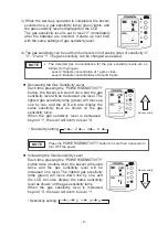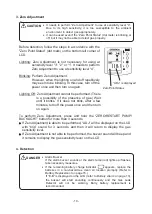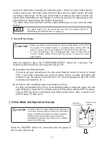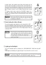
- 5 -
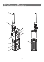
No. Name
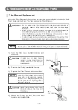
Functions
1
AT-2B Attachment
Gas inlet.
2
DF-114 Drain Filter
Protects the Gas Leak Detector from water, dust,
and other foreign matter.
3
Outlet
Gas outlet to exhaust sampled gas.
4
POWER/SENSITIVITY Button
Turns the power ON and OFF.
Sets the gas sensitivity level.
5
BUZZER Button
Turns the alarm buzzer and operation sound ON
and OFF.
6
ZERO/ RESTART PUMP/
BACKLIGHT Button
Starts Zero Adjustment.
Restarts pump operation after a pump error.
L
ights the LCD backlight.
7
ALARM /ERROR Lamps (red)
Light up or flash when detecting gas leakage.
The
flashing frequency increases as the concentration
of the gas leak increases. The lamps light if the
concentration is very high.
These lamps also flash
when an error occurs in the pump or sensor.
8
Buzzer hole
The buzzer sounds.
9
LCD
Displays the gas sensitivity and messages.
(a)
The remaining battery charge is displayed.
Battery charge:
High . . . . . . . . . . . . . . . . . Low
(b)
It indicates the status of zero adjustment.
(c)
The indicator shows the operation sound. (The
indicator is displayed only when the operation
sound is turned ON.)
(d) The indicator shows the alarm sound.
(The
indicator is displayed only when the alarm
sound is turned ON.)
(e) The pump operation is displayed.
(The indicator
rotates if the pump is operating normally.)
(f)
The gas sensitivity level and errors are
displayed.
10
Gas Sensitivity Lamps (green)
Indicate the gas sensitivity level.
There are five gas
sensitivity levels.
11
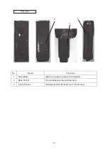
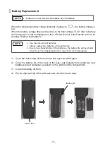
Battery Lid
The cover to the battery compartment.
(
a
)
(
c
)
(
d
)
(
f
)
(
e
)
●
(
b
)
- 4 -
2. Part Names and Functions
1
2
10
6
8
4
3
9
7
5
11


