30
5 INSTALLATION
5
5
.
.
6
6
P
P
r
r
o
o
c
c
e
e
d
d
u
u
r
r
e
e
f
f
o
o
r
r
i
i
n
n
s
s
t
t
a
a
l
l
l
l
a
a
t
t
i
i
o
o
n
n
a
a
n
n
d
d
a
a
d
d
j
j
u
u
s
s
t
t
m
m
e
e
n
n
t
t
a)
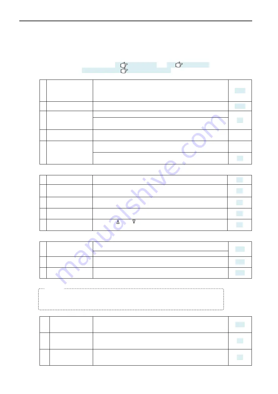
Preparations:
Prerequisites and precautions
•
Install the tester as instructed in
For adjustment, see Section 6.1.4,
See
1 Test pressure source
Connect a pressure source that does not have pressure
fluctuations and that has a sufficient flow capacity for the test. If
the source pressure fluctuates put another pressure regulator
inline before the leak tester.
2 Pilot pressure source Connect dry and clean air regulated to 400 to 700 kPa
3 Prepare a master.
Choose a known non-leaking part and connect it as a master.
A standard Master Chamber can be used if the Master-Preset
compensation is used.
4 Prepare non-leaking
parts
Prepare as many non-leaking parts as possible.
5 Prepare a
Leak Master
Prepare a Leak Master for NG judgement check to verify.
Prepare a Leak Master for leak calibration. It can also be
replaced by a Leak Calibrator.
b)
Setup:
Basic keyboard operation.
See
1 Unlock the keyboard This enables programming the test parameters.
2 Switching remote or
manual operation
The leak tester, when powered on, comes up in remote mode.
Set it in manual mode to enter settings.
3 Select a channel
Select a channel to suit the kind of the tested part and test
conditions.
4 Set a test pressure Use the regulator on the rear of the leak tester and the
front-panel pressure indicator.
5 Set upper and lower
limit test pressures
Using the and buttons on the test pressure gauge, set an
appropriate test pressure range.
c)
Preliminary setup of test parameters:
Setting basic test parameters in Measurement mode.
See
1 Set preliminary stage
timers
Set the CHG, BAL and DET timer.
Allow for a sufficiently long CHG timer (60 seconds or longer).
2 Set preliminary limits There is no need to decide limit settings for the BAL and DET
stages at this point. Their initial values will suffice.
3 Set leak rate unit Pa Use leak rate unit Pa until the equivalent internal volume is
entered.
d)
Leak testing and timer verification:
Verifying that the fixture and the tubing are free from leaks.
See
1
Check for leakage
through visual
bubble inspection
Use the charge and hold feature. Check that the tested part
used is not leaking.
2 Start the leak tester
Run a leak test with the Master-Preset feature turned OFF.
Check that the non-leaking data in the differential pressure (Pa)
unit is sufficiently low.
3
Compare data with
the CHG timer
varied.
Find out the test time in which the data on a non-leaking part
gets stabilized in the vicinity of zero.
Change the BAL and DET timer settings as needed.
Verify that the fixture and tubing comply with the basic test specifications. Determine
the test time needed for measurement with the Master-Preset feature turned OFF to
find out the uncompensated actual value.
NOTE
Содержание LS-1866
Страница 2: ......
Страница 6: ......
Страница 22: ......
Страница 34: ......
Страница 56: ......
Страница 62: ......
Страница 71: ...11 INTERFACE 69 g Typical PLC connection NPN h Typical connection with PLC PNP ...
Страница 88: ......
Страница 89: ...13 APPENDIX 87 1 13 3 APPENDIX 1 13 3 1 1 E EX XT TE ER RN NA AL L A AP PP PE EA AR RA AN NC CE E ...


