


4-21
Installing a new blade
Step 1 -
Select the most suitable saw blade for your workpiece considering the size, shape and
material.
Step 2 - Turn on the machine power by switching to
ON
and turn on the hydraulic system.
Step 3 - Press the
workbed to the left
button and send the workbed all the way to the left end (if
facing the control panel).
Step 4 – Press the
guide arm down
button to lower the guide arm. Open the saw blade cover.
Step 5 - Unclamp the carbide inserts and release the tension controller handle to “relaxed” position.
Step 6 - Open the idle wheel cover.
Step 7 - Lower down the side coolant splash shield.
Step 8 – Loosen the wire brush assembly screws and move the wire brush away from the blade.
Step 9 - Loosen the screw of the workbed crosslink (part A in the above picture) and turn them wide
open.
Step 10 - Lower down the workbed tri-lifters (part B in the above picture) by pulling the handles
downward. (A gentle shake may be necessary.)
Step 11 - Take the blade out through above the tri-lifters and the opening behind the crosslink and
replace with a new blade by inserting through these openings.
Step 12 - After the blade has been properly installed, restore the changes made from step 5 to 9.
Before changing the blade, make note of the direction the blade is running and the blade teeth
is facing.
Remove objects that may stand in the way of blade changing, such as saw blade tension
controller cover.
A
– Workbed
crosslink
B
– Workbed
tri-lifters
Содержание SVT-6070H
Страница 2: ... ...
Страница 4: ... ...
Страница 10: ... ...
Страница 15: ...1 5 Illustration Emergency Stop Emergency Stop ...
Страница 20: ...1 10 Illustration Safety Labels ...
Страница 25: ...2 3 MACHINE PARTS IDENTIFICATION ...
Страница 26: ...2 4 FLOOR PLAN Machine top view Machine side view ...
Страница 36: ... ...
Страница 60: ... ...
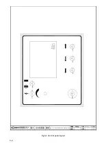
Страница 62: ...5 2 Fig 5 1 Control panel layout ...
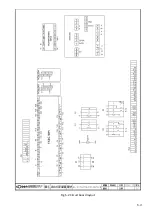
Страница 63: ...5 3 Fig 5 2 Circuit board layout ...
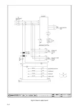
Страница 64: ...5 4 Fig 5 3 Power supply layout ...
Страница 65: ...5 5 Fig 5 4 PLC I O layout ...
Страница 66: ... ...
Страница 67: ...6 1 Section 6 HYDRAULIC SYSTEM HYDRAULIC DIAGRAM ...
Страница 68: ...6 2 Fig 6 1 Hydraulic layout ...
Страница 69: ...7 1 Section 7 BANDSAW CUTTING A PRACTICAL GUIDE INTRODUCTION SAW BLADE SELECTION VISE LOADING BLADE BREAK IN ...
Страница 104: ... ...
Страница 105: ... ...


