


1-6
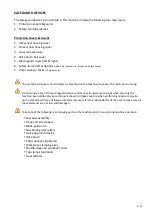
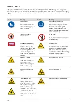
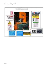
SAFETY LABELS
Safety-related labels mounted on the machine are categorized into the following four categories.
Please read through and understand them before operating the machine. Refer to
Illustration: Safety
Labels.
Label
Meaning
Label
Meaning
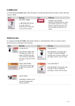
Impact Hazard
WEAR SAFETY SHOES. Do
not approach dropping area
during operation.
Read Operator’s Manual
This manual has important safety
information. Read through it
carefully before operating this
machine to prevent personal injury
or machine damage.
Keep Unauthorized
Personnel Away
Do not step.
Do not stand on the machine or on
the accessories!
DANGER: Running Blade
Blade runs through this
area. Keep your hands away
from a running blade to
avoid severe injury. The
arrow indicates direction of
the blade.
Cutting Hazard
KEEP COVER CLOSED / KEEP HAND
OFF while the blade is running.
Turn power off before opening
cover. Failure to follow the warning
can result in severe injury.
Hazardous Voltage
TURN POWER OFF before
servicing. Failure to
following the warning can
result in severe injury.
Burn Hazard/Hot Surface
Hand Crush/Force from
Above
Crush hazard by vise
Loose Hand Hazard
KEEP HAND OFF. Do not
touch chip conveyor. Failure
to follow the warning can
result in severe injury.
Pinch Point/Hand Entanglement
CAUTION : Class I invisible
Laser Radiation Present.
Avoid direct exposure to
beam.
Содержание SVT-6070H
Страница 2: ... ...
Страница 4: ... ...
Страница 10: ... ...
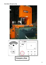
Страница 15: ...1 5 Illustration Emergency Stop Emergency Stop ...
Страница 20: ...1 10 Illustration Safety Labels ...
Страница 25: ...2 3 MACHINE PARTS IDENTIFICATION ...
Страница 26: ...2 4 FLOOR PLAN Machine top view Machine side view ...
Страница 36: ... ...
Страница 60: ... ...
Страница 62: ...5 2 Fig 5 1 Control panel layout ...
Страница 63: ...5 3 Fig 5 2 Circuit board layout ...
Страница 64: ...5 4 Fig 5 3 Power supply layout ...
Страница 65: ...5 5 Fig 5 4 PLC I O layout ...
Страница 66: ... ...
Страница 67: ...6 1 Section 6 HYDRAULIC SYSTEM HYDRAULIC DIAGRAM ...
Страница 68: ...6 2 Fig 6 1 Hydraulic layout ...
Страница 69: ...7 1 Section 7 BANDSAW CUTTING A PRACTICAL GUIDE INTRODUCTION SAW BLADE SELECTION VISE LOADING BLADE BREAK IN ...
Страница 104: ... ...
Страница 105: ... ...


