


4-18
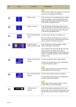
Throat measuring stopper & auxiliary side stoppers
Step 1: Adjust throat measuring stopper
The throat measuring stopper becomes very useful when
determining where to locate the material at.
Position the throat measuring stopper at your desired cutoff
throat size on the measuring tape. After the throat measuring
stopper is firmly secured on the workbed, load your material
and lean it against the stopper to get the desired cutoff throat.
Step 2: Adjust auxiliary side stoppers
Use the auxiliary side stoppers to secure the workpiece from
sliding sideways.
The side stoppers can be positioned at anywhere on the
workbed and can face to the front, back, left or right. Feel free
to utilize these stoppers to maximize workpiece stability during
cutting. After the side stopper is secured (nuts tightened) on the
workbed, use the handle to make fine adjustments.
Top clamp
This top clamp device is a good tool to use when cutting thinner
material with less weight. To be manually adjusted according to
the workpiece dimensions, the top clamp can firmly secure the
workpiece on the workbed when cutting.
A – Base lock nuts & screws:
Relocate the top clamp to anywhere on the movable workbed
by loosening the four sets of base lock nuts & screws, sliding the
top clamp out of the workbed and sliding it to your desired
position and tightening the nuts.
B – Clamp height adjusting screw
Change the height of the top clamp by adjusting this screw.
C – Clamping rod & adjusting screw
Use this screw to adjust how hard you wish to clamp down the
workpiece.
Blade deviation detector
This device detects blade deviation. If the blade deviates beyond
the preset range, the machine will stop automatically. The blade
deviation detected value is displayed and the preset values can
be preset via the HMI touch screen.
Auxiliary side
stopper
Throat
measuring
stopper
Aux. alignment stopper:
handle ^ adjusting screws
C - Clamping
rod & adjusting
screw
B - Clamp
height
adjusting screw
A - Base lock
nuts & screws
Blade deviation
detector
Содержание SVT-6070H
Страница 2: ... ...
Страница 4: ... ...
Страница 10: ... ...
Страница 15: ...1 5 Illustration Emergency Stop Emergency Stop ...
Страница 20: ...1 10 Illustration Safety Labels ...
Страница 25: ...2 3 MACHINE PARTS IDENTIFICATION ...
Страница 26: ...2 4 FLOOR PLAN Machine top view Machine side view ...
Страница 36: ... ...
Страница 60: ... ...
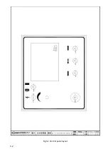
Страница 62: ...5 2 Fig 5 1 Control panel layout ...
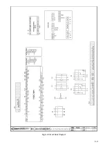
Страница 63: ...5 3 Fig 5 2 Circuit board layout ...
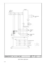
Страница 64: ...5 4 Fig 5 3 Power supply layout ...
Страница 65: ...5 5 Fig 5 4 PLC I O layout ...
Страница 66: ... ...
Страница 67: ...6 1 Section 6 HYDRAULIC SYSTEM HYDRAULIC DIAGRAM ...
Страница 68: ...6 2 Fig 6 1 Hydraulic layout ...
Страница 69: ...7 1 Section 7 BANDSAW CUTTING A PRACTICAL GUIDE INTRODUCTION SAW BLADE SELECTION VISE LOADING BLADE BREAK IN ...
Страница 104: ... ...
Страница 105: ... ...


