


4-8
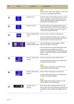
Refer to the table below for descriptions of each function.
No
Item
Function
Description
1
Hydraulic start
When the power is turned on, press this button
to start the hydraulic motor.
A solid yellow icon indicates the hydraulic system
has been turned on.
2
Hydraulic stop
Press this button to turn off the hydraulic motor
immediately.
When the blade is running, the Hydraulic
Stop button is temporarily disabled. You need to
press the
saw blade stop
or workbed to the right
button to stop the blade first.
3
Saw blade start
When the work piece is clamped properly, press
this button to start cutting.
A solid yellow blade icon indicates the blade has
been started.
4
Saw blade stop
Press this button to stop the saw blade.
5
Coolant ON/OFF
Press this button to turn on the coolant pump.
A solid yellow faucet icon indicates the coolant
pump has been turned on.
Press again to turn off the coolant pump.
6
Last cut function
ON/OFF
When the
mode is selected, the blade will
automatically stop and the hydraulic system will
shut down (in 10 seconds) after the current cut is
finished.
7
Manual feeding mode Press this button to switch to the manual feeding
mode. The green solid line indicates the manual
feeding mode has been turned on.
Press the “saw blade start” button (#3 in HMI) to
start the blade. At this time, the table will not
start feeding yet. To perform manual cutting,
after the blade has been started, press and hold
the “cutting start” button (#5 on the control
panel) to start and continue feeding the
workbed. Once letting go of the button, the
workbed will stop feeding to the left but the saw
blade will continue running. To stop the saw
Содержание SVT-6070H
Страница 2: ... ...
Страница 4: ... ...
Страница 10: ... ...
Страница 15: ...1 5 Illustration Emergency Stop Emergency Stop ...
Страница 20: ...1 10 Illustration Safety Labels ...
Страница 25: ...2 3 MACHINE PARTS IDENTIFICATION ...
Страница 26: ...2 4 FLOOR PLAN Machine top view Machine side view ...
Страница 36: ... ...
Страница 60: ... ...
Страница 62: ...5 2 Fig 5 1 Control panel layout ...
Страница 63: ...5 3 Fig 5 2 Circuit board layout ...
Страница 64: ...5 4 Fig 5 3 Power supply layout ...
Страница 65: ...5 5 Fig 5 4 PLC I O layout ...
Страница 66: ... ...
Страница 67: ...6 1 Section 6 HYDRAULIC SYSTEM HYDRAULIC DIAGRAM ...
Страница 68: ...6 2 Fig 6 1 Hydraulic layout ...
Страница 69: ...7 1 Section 7 BANDSAW CUTTING A PRACTICAL GUIDE INTRODUCTION SAW BLADE SELECTION VISE LOADING BLADE BREAK IN ...
Страница 104: ... ...
Страница 105: ... ...


