


4-12
No
Item
Function
Description
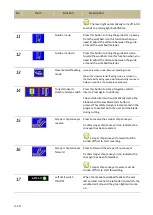
27
Blade speed control
Press “+” to speed up the blade.
Press “-“ to speed down the blade
Cutting status display & setup
When cutting is in operation, press
to enter cutting status display and setup page.
Page 1 – cutting status display and set up 1
This page shows or sets the following information (from
top to bottom):
Set Height – Set the material height
Current blade speed
Current blade feeding speed
Current cutting rate
The current in Amps drawn by the blade
motor displayed on this page if the optional
accessory, Motor Amp Draw, is purchased.
The relative position according to the current
return-to-zero table position.
Current blade life in hours
The green square light on the bottom left
corner indicates the warranty status of the
HMI touch screen. Warranty is one year and
starts counting after 70 hours of operation
after the machine is shipped. Warranty
status light turning to red indicates the HMI
touch screen has expired.
Error messages (highlighted in yellow; can be
cleared by pressing down)
Press HOME to return to the main control menu.
Press NEXT to go to the next setup page.
Press HP Scr. to go to below HP (Horsepower)
monitor screen (for V-drive, an optional accessory
for enhancing cutting efficiency and reducing
cutting vibrations) page.
Blade Life Reset -
Reset the blade life to zero
Содержание SVT-6070H
Страница 2: ... ...
Страница 4: ... ...
Страница 10: ... ...
Страница 15: ...1 5 Illustration Emergency Stop Emergency Stop ...
Страница 20: ...1 10 Illustration Safety Labels ...
Страница 25: ...2 3 MACHINE PARTS IDENTIFICATION ...
Страница 26: ...2 4 FLOOR PLAN Machine top view Machine side view ...
Страница 36: ... ...
Страница 60: ... ...
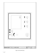
Страница 62: ...5 2 Fig 5 1 Control panel layout ...
Страница 63: ...5 3 Fig 5 2 Circuit board layout ...
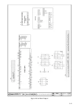
Страница 64: ...5 4 Fig 5 3 Power supply layout ...
Страница 65: ...5 5 Fig 5 4 PLC I O layout ...
Страница 66: ... ...
Страница 67: ...6 1 Section 6 HYDRAULIC SYSTEM HYDRAULIC DIAGRAM ...
Страница 68: ...6 2 Fig 6 1 Hydraulic layout ...
Страница 69: ...7 1 Section 7 BANDSAW CUTTING A PRACTICAL GUIDE INTRODUCTION SAW BLADE SELECTION VISE LOADING BLADE BREAK IN ...
Страница 104: ... ...
Страница 105: ... ...


