


4-10
No
Item
Function
Description
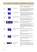
The laser light automatically turns off in 90
seconds to prolong light bulb lifetime.
11
Guide arm up
Press this button to bring the guide arm up away
from the workbed. Use this function when you
need to adjust the distance between the guide
arm and the workbed/material.
12
Guide arm down
Press this button to bring the guide arm down
toward the workbed. Use this function when you
need to adjust the distance between the guide
arm and the workbed/material.
13
Slow material feeding
mode
Used only when under Manual Feeding mode.
When the slow material feeding mode is turned on,
the material feeding speed will dramatically reduce to
help you position the work piece precisely.
14
Tungsten inserts
clamp/unclamp switch
Press this button to clamp tungsten carbide
inserts. Press again to unclamp.
The carbide inserts will automatically clamp the
blade when the saw blade start button is
pressed. This safety design is incorporated in the
program to protect both the user and the blade
during cutting.
15
Scraper chip conveyor
reverse
Press to reverse the scraper chip conveyor.
A solid scraper chip conveyor icon indicates the
conveyor has been reversed.
Scraper chip conveyor forward must be
turned off first to start reversing.
16
Scraper chip conveyor
forward
Press to forward the scraper chip conveyor.
A solid scraper chip conveyor icon indicates the
conveyor has been forwarded.
Scraper chip conveyor reverse must be
turned off first to start forwarding.
17
Left limit switch
ON/OFF
When the movable workbed feeds to the very
left end and touches the left side limit switch, the
workbed will stop and the green light will come
on.
Содержание SVT-6070H
Страница 2: ... ...
Страница 4: ... ...
Страница 10: ... ...
Страница 15: ...1 5 Illustration Emergency Stop Emergency Stop ...
Страница 20: ...1 10 Illustration Safety Labels ...
Страница 25: ...2 3 MACHINE PARTS IDENTIFICATION ...
Страница 26: ...2 4 FLOOR PLAN Machine top view Machine side view ...
Страница 36: ... ...
Страница 60: ... ...
Страница 62: ...5 2 Fig 5 1 Control panel layout ...
Страница 63: ...5 3 Fig 5 2 Circuit board layout ...
Страница 64: ...5 4 Fig 5 3 Power supply layout ...
Страница 65: ...5 5 Fig 5 4 PLC I O layout ...
Страница 66: ... ...
Страница 67: ...6 1 Section 6 HYDRAULIC SYSTEM HYDRAULIC DIAGRAM ...
Страница 68: ...6 2 Fig 6 1 Hydraulic layout ...
Страница 69: ...7 1 Section 7 BANDSAW CUTTING A PRACTICAL GUIDE INTRODUCTION SAW BLADE SELECTION VISE LOADING BLADE BREAK IN ...
Страница 104: ... ...
Страница 105: ... ...


