background image

Installation Instructions

Issue 1, September 2009

UCAO cable strain relief
for 2 cables up to Ø7mm

Montageanweisung

Ausgabe 1, September 2009

UCAO Kabel-Zugabfangung
für 2 x Kabel bis Ø7mm

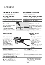
1. Kabel vorbereiten

An der Zugabfangung können 2 Kabel
mit einem Ø von max. 7mm befestigt
werden.
Kabelmantel auf der benötigten Länge
absetzen. Die Zentralelemente der
Kabel auf ca. 15mm einkürzen.

These installation instructions are provided as guidance for the
trained craftsperson carrying out the installation.

Diese Montageanweisung soll dem ausgebildeten Monteur, der
die Installation durchführt, als Leitfaden dienen.

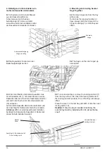
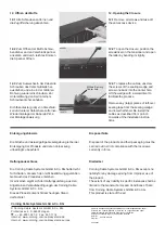
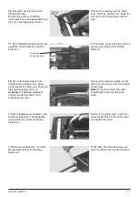
2. Montage der Zugabfangung

Die Kabel mit jeweils zwei Kabel-
bindern auf den Krallenblechen
befestigen.
Zentralelemente, wie darge-
stellt, bis zum Anschlag unter
den Klemmbügel schieben und
mit der Sechskantmutter
festziehen.
Falls nur ein Kabel eingesetzt
wird, ist ein Blindstopfen zu
verwenden.
Diesen ebenfalls mit Kabel-
bindern sichern.

15mm

ucao_0096

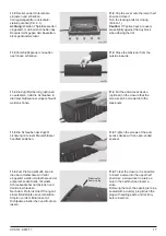
2. Mounting the strain relief

Fix the cables with two cable ties each
on the spiked plates.

Push the central elements (as
shown) until they stop under the
clamp and tighten with the hex
nut.

A dummy plug must be used if
only one cable is inserted.

This must also be fixed with cable
ties.

Corning Cable Systems GmbH & Co. KG

© Corning Cable Systems GmbH & Co. KG,
Profilstrasse 4, D-58093 Hagen

     ++ 49-2331-357-0 Fax: 357-1118

Internet: www.corning.com/cablesystems

Gedruckt  in der Bundesrepublik Deutschland auf  sauerstoffgebleichtem
Papier.
Printed  in  the  Federal  Republic  of  Germany  on  oxygen-bleached  paper.
Liefermöglichkeiten und technische Änderungen vorbehalten.
Subject  to  availability.  Right  of  modification  reserved.
Best.-Nr.: S45754-L4003-P837
Order  No.:

27.08.2009

Entsorgungshinweis

Die örtliche und aktuell gültige Gesetzgebung ist bei der
Entsorgung der Produkte und deren Verpackung unbedingt zu beachten!

Haftungsausschluss

Die Corning Cable Systems GmbH & Co. KG haftet nicht für
Schäden, die durch den nicht bestimmungsgemäßen Gebrauch des Produktes entstehen.
Im einzelnen ergibt sich der Haftungsumfang  aus den Allgemeinen Verkaufsbedingungen
der Corning Cable Systems GmbH & Co. KG.
Diese Produkt entspricht dem heutigen Stand der Technik!

Disposal Note

Disposal of the products and their packaging must be carried out
in strict compliance with the local laws currently in force.

Disclaimer

Corning Cable Systems GmbH & Co. KG accepts no liability for any damage arising from
improper use of the product.
The extent of any liability in specific instances shall be limited to the General Terms and
Conditions of Sale from Corning Cable Systems GmbH & Co. KG.
This product is state of the art.

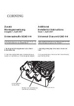
1. Prepare cable

2 cables with 7 mm max. Ø can be
fixed on the strain relief.

Strip the cable sheath to the required
length. Shorten the central elements
of the cables to approx.15 mm.

Содержание UCAO 4-9 MFT 7

Страница 1: ...ührt als Leitfaden dienen Montageanweisung Ausgabe 1 Juni 2006 Universalmuffe UCAO 4 9 MFT 7 Installation Instructions Issue 1 June 2006 Universal Closure UCAO 4 9 MFT 7 These instructions are provided as a guideline for the trained craftsperson carrying out the installation ...

Страница 2: ...Anlagen Einrichter Betreiber der Kommunikationseinrichtung endgültig zu bestimmen und verantwortlich auszuweisen z B Anbringen normgerechter Warnschilder nach DIN EN IEC 60825 1 gültige Ausgabe Beachtung der BGV B2 Laserstrahlung gültige Ausgabe Bei Änderung der technischen Daten die den Gefährdungsgrad beeinflussen sind bei Notwendigkeit die Warnungen entsprechend anzupassen und Arbeitssicherheit...

Страница 3: ...h 7 Schrauben für Verschlußkeil 8 Blindstopfen 9 Wickellehre 10 Erdungsschraube 11 Schirmverbindungsleitung 12 Kassettenhalter 13 Halter für Verschlusselement 14 Montageanweisung 1 Contents of Closure Pack 1 Closure with tensioners 2 Strain relief with screw and contact plate 3 Sealing wedge with metal bracket 4 Sealing tape 5 Sealing 6 Cleaning tissue 7 Screws for sealing wedge 8 Dummy plug 9 Wra...

Страница 4: ...l uca_251 1 4 1 2 1 3 5 3 Technische Daten 3 Technical Data m m n i e ß a M m m n i s n o i s n e m i D l e b a k h c a f n i E g n u r h ü f n i e y r t n e e l b a c e l g n i S l e b a k h c a f r h e M g n u r h ü f n i e y r t n e e l b a c i t l u M m m 1 2 Ø n e s h c u b f p o t S g n u r h ü f n i e e t i e S e j e l b a c d n a l G e d i s h c a e y r t n e n e g ö m r e v s g n u s s a ...

Страница 5: ...ttenes Kabel B 4 2 Strip cable sheath as per instruc tions in the table Cut cable A Uncut cable B Verriegelungsstift geschlossen Locking bolt closed 4 3 Bei Kabeln Ø größer 8 mm Kabelmantel beitseitig einschneiden L 30 mm B max 28 mm Die Maße können mit Hilfe der Wickel lehre markiert werden Kabelmantellappen mit Zange flach drücken 4 3 For cable diameters which exceed 8 mm cut cable sheath on bot...

Страница 6: ...hirm verbindung an der Abfangung festzie hen 4 4 Insert cable sheath flaps into the strain relief Fasten the screw with the shield connection on the strain relief 4 5 In die Mehrfachabfangung gesondert zu bestellen können bis zu 4 Kabel mit einem Ø von max 8 mm eingeführt werden Kabel mantel ca 10 mm durch die Abfangung schieben und festziehen 4 5 Up to 4 cables with a Ø of max 8 mm can be inserte...

Страница 7: ...Einbau für Zentralelement und Maxibündel genutzt werden 5 Installing the Central Member Strain Relief 5 1 Prior to inserting the cables insert the strain relief for the central mem bers into the lower half shell and fasten it with a screw The strain relief can be used either for the central member or for the central buffer by changing the side it is fitted on Für das Zentralelement For the central...

Страница 8: ...6 2 Insert the cable into the lower half shell Unused cable entries are to be sealed with a dummy plug which is wrapped with sealing tape in the same way as the cables Blindstopfen Dummy plug 6 3 Verschlußkeil mit Bügel aufset zen Schrauben wechselseitig lang sam eindrehen bis der Keil geschlos sen ist Keil muß bündig mit der Halbschale abschließen 6 3 Attach the sealing wedge with the bracket slo...

Страница 9: ...t 5 1 Maxibündel auf benötigte Länge kürzen und in die Abfangung einfüh ren Die Fasern laufen nach vorne durch die Abfangung 6 7 To ground the central member first replace the plastic screw with a metal screw Then proceed to ground the central member by running the shield connection lead beneath the metal screw Accessory kit with metal screw and shield connection lead 6 8 The strain relief is to b...

Страница 10: ...end dem Kabeldurchmesser auswählen Kabeldurchmesser 8 10 mm Zahn scheibe und Dichtung mit kleiner Öffnung Kabeldurchmesser 11 13 mm Zahn scheibe und Dichtung mit großer Öffnung 7 4 Select sealing and washer according to the cable diameter Cable diameter 8 10 mm washer and sealing with small opening Cable diameter 11 13 mm washer and sealing with large opening 7 3 Push the threaded plug on the cabl...

Страница 11: ... Kabel in die Stopfbuchse einführen Den Kabel mantellappen mit Hilfe einer Zange an die Zugabfangung anformen Achtung Die Kabelmantellappen dürfen vor dem Einführen nicht aufgebogen werden 7 8 Insert the prepared cable into the gland Use the pliers to form the cable sheath flaps Note Do not bend open the cable sheath flaps before inserting the cable 7 9 Die Zugabfangung einsetzen den Kabelmantella...

Страница 12: ... 25 mm 9 Slack storage mininimum bend radius 25 mm 9 Zugabfangung für Bündeladern 10 Strain relief for buffer tubes 10 Schwenkpunkt 12 Hinge point 12 Taschen für Verschluss bzw Befestigungselement 13 Pockets for locking and mounting elements 13 Faserführungskanal 14 Fiber guide channel 14 Bohrung für O Pack 15 Hole for O Pack 15 Bohrung für Befestigungsschraube 16 Hole for securing screw 16 Befest...

Страница 13: ...der Bündeladern Strain relief For securing buffer tubes 11 Verschlusselement Zum Befestigen des Silikon Schutz bei Fasereinführung Locking element For securing the silicone protection on fiber entry 12 Schwenkpunkt Zum Schwenken der Kassette auf einem O Pack Hinging point For hinging the tray on an O Pack 13 Taschen für Verschluss bzw Befestigungselement Zum Befestigen von Pos 1 oder Pos 17 Pocket...

Страница 14: ...emente 13 einrasten Auf die letzte Kassette den Deckel aufsetzen und am Anschlag für Deckelverschluß 18 einrasten Achtung Wird nur eine Kassette zum Spleißen benötigt muß die zweite Kassette mit Deckel als oberer Schutz installiert werden 9 Mounting and Locking Several TraysTogether 9 1 Remove hinges 3 from the tray with a knife To interlink the required number of trays always latch the hinges to ...

Страница 15: ...deladern einsetzen 10 Installing the Fiber Optic Components 10 1 Insert the tray holder and the holder for locking element into the lower half shell as shown in the sketch Then insert the buffer holders uca_252 Kassettenhalter Tray holder Halter für Verschlusselement Holder for locking element uca_254 uca_253 Bündeladerhalterung Buffer holder Bündeladerhalterung Buffer holder Verschlußelement Lock...

Страница 16: ...sert the sealing into the lower half shell with the groove facing upwards Dichtung Sealing Untere Halbschale Lower half shell Nut Groove 10 3 Kassettenhalter herunterklappen und am Verschlußelement einrasten 10 2 Splice the fibers as required secure the splice trays in the tray holder and fasten the buffers beneath the holders 10 2 Fasern nach Bedarf spleißen Spleißkassetten im Kassettenhalter abl...

Страница 17: ...chraubendreher durchstoßen und Ventil einschrauben Nach dem Prüfen ist die Öffnung mit einem Blindstopfen zu verschließen Stopfen vor dem Eindrehen mit Dichtpaste einstreichen und trocknen lassen 11 6 To test the closure it is possible to insert a valve into the upper half shell Use a screwdriver to pierce a hole in the half shell and insert a valve Following the test the opening is to be sealed w...

Страница 18: ...be limited to the General Terms and Conditions of Sale from Corning Cable Systems GmbH Co KG This product is state of the art Disposal Note Disposal of the products and their packaging must be carried out in strict compliance with the local laws currently in force 12 Öffnen der Muffe 12 1 Alle Schrauben entfernen und die Zugriffsicherung abnehmen 12 Opening the Closure 12 1 Remove all screws and t...

Страница 19: ...Montage Minikabel 2 1 Kabelmantel auf der benötigten Länge absetzen und das Zentral element auf ca 25 mm einkürzen 25mm ucao_0096 2 2 Das Zentralelement wie darge stellt bis zum Anschlag unter die Zentralelement Zugabfangungschie ben und festziehen Das Kabel mit dem kleinen Kabel binder wie dargestellt sichern ucao_0098 1 2 3 4 ucao_0093 1 Packagecontents 1 Cable Strain relief 2 Cable ties for min...

Страница 20: ...d der Technik Entsorgungshinweis Die örtliche und aktuell gültige Gesetzgebung ist bei der Entsorgung der Produkte und deren Verpackung unbedingt zu beachten Disclaimer Corning Cable Systems GmbH Co KG accepts no liability for any damage arising from improper use of the product The extent of any liability in specific instances shall be limited to the General Terms and Conditions of Sale from Corni...

Страница 21: ... darauf zu achten dass der Kabelmantel mit einem Messer in eine runde Form in Längsrichtung abgeschabt wird Es dürfen keine Längsriefen zurückbleiben Caution With figure 8 cables make sure to scrape the cable sheath into a round shape with a knife in longitudial direction Ensure that no longitudinal groves are left Aramidgarn Aramid yarn Zentralelement Central member 35 mm 2 Die Kabelabfangung im ...

Страница 22: ...r Corning Cable Systems GmbH Co KG accepts no liability for any damage arising from improper use of the product The extent of any liability in specific instances shall be limited to the General Terms and Conditions of Sale from Corning Cable Systems GmbH Co KG This product is state of the art Disposal Note Disposal of the products and their packaging must be carried out in strict compliance with t...

Страница 23: ...ng soll dem ausgebildeten Monteur der die Installation durchführt als Leitfaden dienen 1 Montage des Dichtungsbandes in der unteren Muffenhalbschale 1 1 Die untere Muffenhalbschale im Kabeleinführungs bereich von der Mitte aus mit Dichtungsband belegen 1 Mounting sealing tape to the lower closure half shell 1 1 Apply sealing tape to the lower half in the cable entry area from the center Dichtungsb...

Страница 24: ...5754 L4003 P431 Haftungsausschluss Die Corning Cable Systems GmbH Co KG haftet nicht für Schäden die durch den nicht bestimmungsgemäßen Gebrauch des Produktes entstehen Im einzelnen ergibt sich der Haftungsumfang aus den Allgemeinen Verkaufsbedingungen der Corning Cable Systems GmbH Co KG Dieses Produkt entspricht dem heutigen Stand der Technik Entsorgungshinweis Die örtliche und aktuell gültige G...

Страница 25: ...o KG Profilstrasse 4 D 58093 Hagen 49 2331 357 0 Fax 357 1118 Internet www corning com cablesystems Gedruckt in der Bundesrepublik Deutschland auf sauerstoffgebleichtem Papier Printed in the Federal Republic of Germany on oxygen bleached paper Liefermöglichkeiten und technische Änderungen vorbehalten Subject to availability Right of modification reserved Best Nr S45754 L4003 P837 Order No 27 08 20...

Страница 26: ... KG Este producto cumple los estándares técnicos actuales Instrucciones de montaje 1ª edición septiembre 2009 Dispositivo antitracción UCAO para 2 cables de hasta 7 mm de Ø Instructions de montage 1ère édition septembre 2009 Serre câble UCAO pour 2 câbles Ø7mm maxi 1 Préparer le câble Il est possible de fixer au serre câble 2 câbles de 7 mm Ø maxi Retirer la gaine sur la longueur nécessaire Raccou...

Страница 27: ... tube 1 Fan out adapter 2 Grommet from 5 3 to 10 3 mmØ 3 Buffer tubes 900 mm long 4 Cable ties 5 Installation instructions 2 Den benötigten Kantenschutz über die gereinigten Fasern auf das Zentrahlrohr schieben Kantenschutz Grommet These instructions are provided as guidance for the trained craftsperson Diese Anweisung soll dem ausgebildeten Monteur als Leitfaden dienen 1 Prepare the cable accordi...

Страница 28: ...om cablesystems de Internet www corning com cablesystems europe Gedruckt in der Bundesrepublik Deutschland auf sauerstoffgebleichtem Papier Printed in the Federal Republic of Germany on oxygen bleached paper Liefermöglichkeiten und technische Änderungen vorbehalten Subject to availability Right of modification reserved Best Nr Order No S46998 A2 P881 10 04 2007 3 Push the fan out adapter over the ...

Страница 29: ...os de fibras 900 mm de longitud 4 Sujetacables 5 Instrucciones de montaje 1 Preparar el cable según lo indicado en las instrucciones del manguito utilizado y desaislar el tubo central Instructions de montage Edition 1 Juillet 2002 Adaptateur de distribution pour maxitubes Instrucciones de montaje Edición 1 Julio 2002 Adaptador de distribución para maxigrupos Les présentes instructions sont destiné...

Страница 30: ...ar el adaptador de distribución sobre el protector de cantos a través de las fibras y apretar 4 Fijar el adaptador de distribución mediante un sujetacables al dispositivo de retención de cables del manguito utilizado 5 Limpiar cuidadosamente las fibras desaisladas y dividirlas en la cantidad de grupos requeridos con un máximo de 12 fibras cada uno Introducir los grupos de fibra óptica en los tubos...

Отзывы: