Technical Support Manual – 05/2018 Rel. 2.1.3
Page 33
8. ACOUSTIC SIGNALS
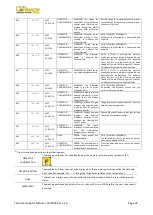
The machine emits different acoustic signals based on its status. The acoustic signals are listed in table T8.1.
Table T8.1: Acoustic signals
Signal
Meaning
Notes
Short beep
Selecting a program or a function
Long beep
Acquisition
•
Acquisition of a value;
•
Acquisition of the wheel dimensions in the STD,
ALU1 Program Types.
Long beep +
1 Short beep
Acquisition of internal plane in ALS1 or ALS2 Program
Types.
Long beep +
2 Short beeps
Acquisition of external plane in ALS1 or ALS2 Program
Types.
Double beep
Warning
A particular condition has occurred that requires the
operator's attention.
Triple beep
Function not available or Error
The requested function is not available or that an error
condition has occurred.
Short beep + long beep
Storing one or more values in the permanent
memory (eeprom) of the circuit board
One or more values have been stored in the permanent
memory of the circuit board (for example, at
completion of calibration phases).
Intermittent beep
Adjustment
Signal used in some service programs to simplify the
adjustment of sensors.
The acoustic signal is also heard for about two seconds at machine start up allowing the operator to check the operation of the alarm
(buzzer).
9. SPECIAL VISUAL SIGNALS
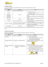
The machine gives special visual signals in certain cases. The special visual signals are listed in table T9.1.
Table T9.1: Special visual signals
Signal
Meaning
Notes
Three dots lit on one or
both displays
Imbalance exceeds 999 grams.
This signal can be triggered due to:
•
Lack of machine calibration;
•
Incorrect measuring of the wheel dimensions;
•
Incorrect setting of the Wheel Type;
•
Incorrect setting of the Program Type.
Flashing green STBY LED
The machine is in the STAND-BY mode.
All LEDs and displays are switched off. To exit the
STAND-BY mode press any button
(except for [P7]
).
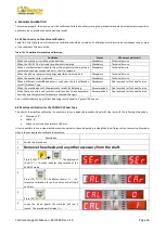
The left (or right) display
is flashing
a)
Waiting on the user's command;
b)
The Diameter or Width sensor is not
calibrated.
a)
The user's command may be the pressing a key
to confirm or continue the procedure in progress
or the selecting of a value or a menu option.
b)
Call the technical support to carry on with the
calibration of the Diameter and Width sensor. To
continue with the operation, you can
temporarily disable the sensors by pressing
[F+P2]
.
Содержание MEC 10
Страница 1: ...WHEEL BALANCERS MEC 5 MEC 10 MEC 15 MEC 20 TECHNICAL SUPPORT MANUAL UK...
Страница 2: ......
Страница 38: ......


