Technical Support Manual – 05/2018 Rel. 2.1.3
Page 29
9
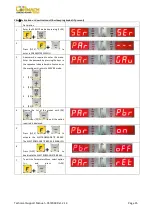
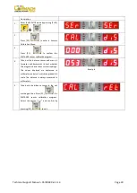
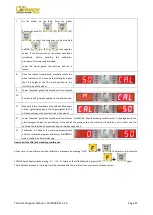
At the end of the spin, the machine will display the
writing
h12 CAL
.
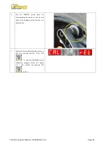
10
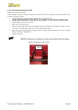
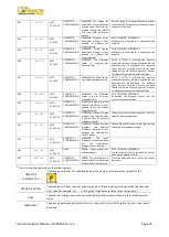
Apply the calibration weight on the internal side as
shown in the picture. The calibration weight must be
applied on the hole in the upper side. Move the
motorcycle adaptor to a stable vertical position with
the calibration weight in the upper side as shown in
the picture. If the weight position is significantly
different from the vertical position the machine will
not spin and i twill display an error code
Err 043
.
11
Lower the wheel guard: the machine will run a spin.
12
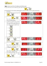
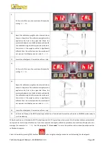
At the end of the spin, the machine will display the
writing
CAL h12
.
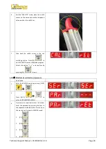
13
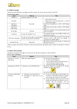
Apply the calibration weight on the external side as
shown in the picture. The calibration weight must be
applied on the hole in the upper side. Move the
motorcycle adaptor to a stable vertical position with
the calibration weight in the upper side as shown in
the picture. If the weight position is significantly
different from the vertical position the machine will
not spin and i twill display an error code
Err 043
.
14
Lower the wheel guard: the machine will run a spin.
15
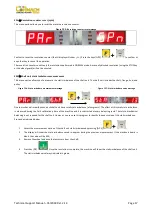
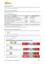
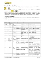
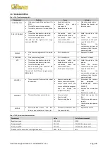
At the end of the spin the MOTO wheel type calibration is finished and the machine will switch to NORMAL mode, ready to
run the balancing.
When the calibration is finished the MOTO wheel type and ALU1 Program Type value are set. Also the wheel data are automatically
set by machine for this type of calibration. If you have anomalies during the calibration procedure, the machine will display the error
message (for example
Err 025
). See the paragraph
“7. Error codes”
to solve the problem and continue/repeat/cancel the
calibration in progress.
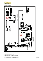
Spins interrupted by pressing [P10] key Stop
or by rising the wheel guard can be run by lowering the wheel guard.
Содержание MEC 10
Страница 1: ...WHEEL BALANCERS MEC 5 MEC 10 MEC 15 MEC 20 TECHNICAL SUPPORT MANUAL UK...
Страница 2: ......
Страница 38: ......

