background image


Technical Support Manual – 05/2018 Rel. 2.1.3                         

Page 26 

6. MACHINE CALIBRATION 

To function properly, the machine must be calibrated. Calibration allows storing the mechanical and electrical parameters specific to 
each machine so provide the best balancing results.  
 

6.1 When to carry out machine calibration 

Table T6.1 lists the cases in which machine calibration should be carried out. Calibration must be carried out whenever one or more 
of the conditions listed are active. 

Table T6.1: 

Conditions for machine calibration


Condition 

Status 

Who must perform it 

When the machine is installed at the final user 

Mandatory 

Technical Service 

When the CPU-C1C.X electronic circuit board is replaced 

Mandatory 

Technical Service 

When a mechanical part linked to the pick-up signals (pick-up, pick-up 
compression springs, suspension unit + shaft) is replaced 

Mandatory 

Technical Service 

When the pick-up compression springs adjustment are modified 

Mandatory 

Technical Service 

When the encoder disc is replaced 

Mandatory 

Technical Service 

When a different motorbike adaptor is used since the last calibration 
for MOTO Wheel Type 

Mandatory 

Final user and/or Technical Service 

When the machine doesn’t show accurate results for balancing 

Recommended 

Final user and/or Technical Service 

When there are wide and constant variations due to environmental 
humidity and temperature (for example seasonal changes) 

Recommended 

Final user and/or Technical Service 

A non-calibrated machine provides balancing results equal to 0 grams (0.0 ounce). 
 

6.2 Machine calibration for the CAR/SUV Wheel Type 

To perform the machine calibration it is necessary to use a balanced complete wheel with steel rim with the following dimensions:  


Diameter: 15”. 


Width: 6”. 


Distance: as close as possible to 100 mm. 

It is also possible to use a wheel with dimensions similar to those indicated, provided that the difference is not excessive. Aluminum 
wheels cannot be used to calibrate the machine. 


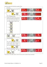
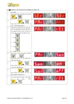
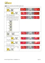
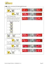
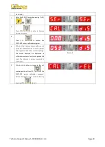
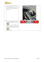
Description 


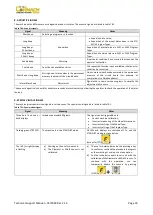
Switch the machine on. 


Remove the wheels and any other accessory from the shaft.


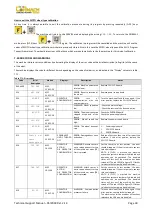
Press [F+P3]  

. The display will 

show 

SER SER

 which indicates the activation of the 

SERVICE mode. 


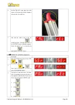
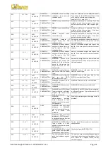
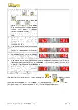
Press [P3]  

. The display shows 

CAL CAR 

(machine calibration for auto-vehicles and off-road 
vehicles). 


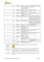
Press [P3]  


Lower the wheel guard: the machine will run a 
launch. The machine will display 

CAL  1


Содержание MEC 10

Страница 1: ...WHEEL BALANCERS MEC 5 MEC 10 MEC 15 MEC 20 TECHNICAL SUPPORT MANUAL UK...

Страница 2: ......

Страница 3: ...brake if present 15 iLL Activation or deactivation of the illumination LEDs if present 16 SPn Revolution counter reset spin 17 ShF Shaft unit static imbalance measurement 17 4 PICK UP SPRING PRE CHARG...

Страница 4: ...ams that can be used to detect any anomaly The TEST programs are grouped inside the Test Programs menu Figure F2 1 Machine use controls Table T2 1 Settings programmes and Menu available in the SERVICE...

Страница 5: ...eactivation Ret Return to SERVICE mode 4 Press keys F P9 to confirm the option 5 To exit the TEST Programs Menu select the Menu option Ret and press keys F P9 ENC ENCODER disc test This menu option al...

Страница 6: ...ominal rotation speed indicated in table T10 2 refers to a frequency of 50 Hz If the frequency in that country is 60 Hz the rotation speed will be 20 higher provided that the motor and pulley are the...

Страница 7: ...15 and MEC 20 If both pick up signals differ from but are similar to the values indicated in table T10 2 check if The dimensions of the wheel are different from those of the reference wheel The wheel...

Страница 8: ...nd F3 11 Figure F3 10 Keyboard Test Message Figure F3 11 Keyboard value message Press one key at a time to make sure that the control corresponds to the key For technical reasons key P7 F cannot be te...

Страница 9: ...on if present Description 1 Enter the SERVICE mode by pressing F P3 2 Press F P9 to enter in TEST Programs menu 3 Browse the list of the Menus with keys P4 or P5 until the option required is displayed...

Страница 10: ...e Menus with keys P4 or P5 until the option required is displayed Press F P9 to confirm the option 4 Press F P9 to DEACTIVATE THE WHEEL GUARD MICRO SWITCH In this way it is possible to run a launch by...

Страница 11: ...ion 4 Browse the list of the menus with keys P4 or P5 until the option required is displayed The menu options available are listed in table T3 1 Table T3 1 Parameters Menu Option Options Description N...

Страница 12: ...1 Enter the SERVICE mode by pressing F P3 2 Press F P5 to enter in PARAMETERS MENU 3 A password is required to enter this menu Enter the password by pressing the keys in the sequence indicated within...

Страница 13: ...ccording to the pictures provided below Remove external sensor from the packaging There are holes at the back of the wheel balancer to attach the external sensor Place the flange of external sensor on...

Страница 14: ...n the sequence indicated within 5 seconds or the machine will return to SERVICE mode 1 P1 2 P4 3 P2 4 P5 4 Browse the list of the menus with P4 or P5 until the option required is displayed 5 Press F P...

Страница 15: ...sword is required to enter this menu Enter the password by pressing the keys in the sequence indicated within 5 seconds or the machine will return to SERVICE mode 1 P1 2 P4 3 P2 4 P5 4 Browse the list...

Страница 16: ...sword is required to enter this menu Enter the password by pressing the keys in the sequence indicated within 5 seconds or the machine will return to SERVICE mode 1 P1 2 P4 3 P2 4 P5 4 Browse the list...

Страница 17: ...this menu Enter the password by pressing the keys in the sequence indicated within 5 seconds or the machine will return to SERVICE mode 1 P1 2 P4 3 P2 4 P5 4 Browse the list of the menus with P4 or P5...

Страница 18: ...RVICE mode by pressing F P3 2 Press F P5 to enter in PARAMETERS MENU 3 A password is required to enter this menu Enter the password by pressing the keys in the sequence indicated within 5 seconds or t...

Страница 19: ...nt message Figure F3 7 Static imbalance value message Due to mechanical imperfections each shaft unit has a small static imbalance a few grams The effect of this small static imbalance is measured dur...

Страница 20: ...3 Manually tighten the hex screw until it stops 4 Repeat step 1 for the other pick up 5 Make sure that the springs and hex screws are perpendicular to the pick up support unit If required loosen the s...

Страница 21: ...Calibration Menu 8 Select another menu and press P1 to confirm Option Ret allows you to exit the Sensor Calibration Menu DIS Distance Sensor The distance sensor does not require any calibration or adj...

Страница 22: ...out the distance sensor and move it forwards and backwards to test whether the magnetic band takes correct readings The values displayed are expressed in millimeters and must match the graduated scale...

Страница 23: ...to enter the Sensors Calibration Menu 3 Browse the list of the menus with P4 or P5 until the option required is displayed 4 Press P1 to confirm the DIAMATER sensor calibration program Position the dis...

Страница 24: ...the distance diameter sensor on the rim and check that displayed value matches the diameter rim 7 Take back the distance diameter sensor in the not working position Press P1 to exit the DIAMETER sens...

Страница 25: ...3 Browse the list of the menus with P4 or P5 until the option required is displayed 4 Press P1 to confirm the WIDTH sensor calibration program Square up the width sensor and the machine will display t...

Страница 26: ...to exit the WIDTH sensor calibration program Select the option Ret and confirm by pressing P1 to exit SON SONAR device calibration if present Description 1 Enter the SERVICE mode by pressing F P3 2 P...

Страница 27: ...sensor to the SONAR device is displayed 6 By means a measuring tape measure the distance between the diameter sensor gauge and the SONAR DEVICE Read the measured value 7 Change the value with the P4...

Страница 28: ...d since the last calibration for MOTO Wheel Type Mandatory Final user and or Technical Service When the machine doesn t show accurate results for balancing Recommended Final user and or Technical Serv...

Страница 29: ...50 appears on the right display Apply the 50 g weight at the 12 o clock position on the external side of the wheel 12 Lower the wheel guard the machine will run a launch For MEC 20 keep the wheel guar...

Страница 30: ...he motorcycle wheels proceed as follows Description 1 Switch on the machine 2 Mount the MOTO flange on the shaft 3 Make sure that the hole on the shaft adaptor and one of the holes of adaptor itself a...

Страница 31: ...in the upper side Move the motorcycle adaptor to a stable vertical position with the calibration weight in the upper side as shown in the picture If the weight position is significantly different from...

Страница 32: ...the end of the launch Check the ENCODER board Check the power supply board 013 SPD HIG MEC 5 10 15 20 ERROR Wheel speed too high Replace the power supply board 014 NO SPN MEC 5 10 15 20 ERROR The whe...

Страница 33: ...t be on the external side Remove the weight from the internal side and repeat the launch If the error persists contact technical support 030 CAR CAL MEC 5 10 15 20 OPERATOR CONFIRMATION WARNING Lack o...

Страница 34: ...tion point ONLY TECHNICAL PERSONNEL Re position the Diameter sensor into the correct calibration position 050 NO HYD MEC 5 10 15 20 OPERATOR CONFIRMATION WARNING Absence of wheel external imbalance It...

Страница 35: ...in some service programs to simplify the adjustment of sensors The acoustic signal is also heard for about two seconds at machine start up allowing the operator to check the operation of the alarm buz...

Страница 36: ...isplayed is 0 When knocking the machine the values do not change The value of the VFC must range between 40 0 44 0 Connection cable not welded on the pick up Connection cable not connected to CPU Pick...

Страница 37: ...Technical Support Manual 05 2018 Rel 2 1 3 Page 35 11 WIRING DIAGRAM It is possible to order the following codes 1 Cod 21201028 CPU C1C X BOARD 2 Cod 21201019 PWRB2X POWER SUPPLY BOARD 1 2...

Страница 38: ......
Страница 39: ...CORMACH S r l via A Pignedoli 2 42015 CORREGGIO RE ITALY Tel 39 0522 631274 Fax 39 0522 631284 e mail cormach cormachsrl com www cormachsrl com...

Отзывы:

Похожие инструкции для MEC 10