the restrictive device and the compressor suction nozzle
must be at least ten times the swept cylinder volume.
On liquefied gas applications such as LPG, it is of
extreme importance to prevent the entry of liquid into the
compressor. Installing a liquid trap on the inlet side will
prevent liquid from entering the compressor (see section
1.4). It is of equal importance to protect the discharge
side of the compressor from liquid entry. This may be
done by installing a check valve on the discharge side of
the compressor combined with a piping design that does
not allow liquid to gravity drain into the compressor.
For vapor recovery applications, be certain to install
a check valve on vapor lines discharging to the liquid
space of the tank.
All piping must be in accordance with the laws and codes
governing the service. In the United States, the following
codes apply:
For LP Gas—The National Fire Protection Association
Pamphlet No. 58, Standard for the Storage and Handling
of Liquefied Petroleum Gases.
For Ammonia—The American National Standards
Institute, Inc., K61.1-1989, Storage and Handling of
Anhydrous Ammonia.
Install, use, and maintain this equipment according to
Corken instructions and all applicable federal, state, and
local laws and codes.
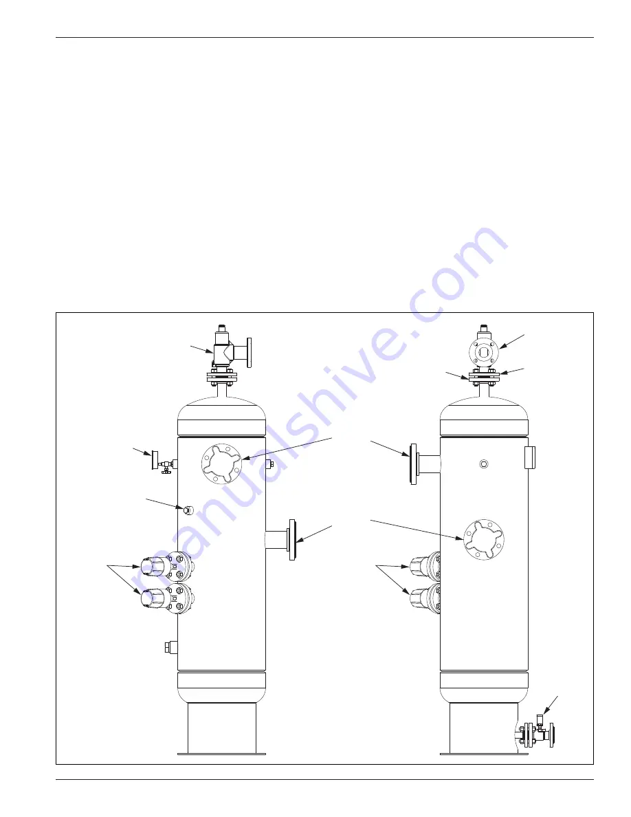
2 .4 Liquid Trap
Compressors are designed to pressurize gas and not pump
liquids. The entry of even a small amount of liquid into the
compressor will result in serious damage to the compressor.
A liquid trap (scrubber) must be installed in the suction
piping and discharge line if condensate can drain back
to the compressor.
Pressure gauge
(0–400 PSI)
Liquid level
switches
1/2" NPT openings
for sight glass
ASME Class 300 RF
Liquid level
switches
Relief valve
Manual
drain valve
ASME
Class 300
RF 3"
outlet
ASME
Class 300
RF 3"
inlet
ASME
Class 300
RF inlet
ASME
Class 150
RF outlet
Figure 2.4
7


