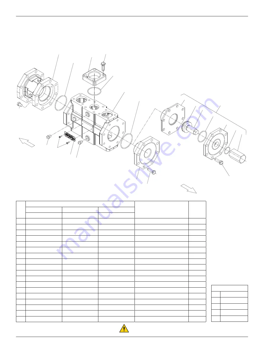
Appendix D—Cylinder Head Assembly Details (HG600/THG600 Series)
3 .25", 4", and 5" Cylinder Head
Cylinder—Bill of Materials
Ref
No .
Cylinder Size
Description
Qty . per
Cylinder
3 .25"
4"
5"
Part No .
Part No .
Part No .
1.
2-236_
a
2-242_
a
2-250
O-ring
2
2.
3793-2S
3793-2S
3793-2S
Flange
2
3.
7001-150NC175A
7001-050NC175A
7001-050NC175A
Bolt (hex head, 1/2"–13 x 1-3/4")
8
4.
2-231_
a
2-231_
a
2-231_
a
O-ring
2
5.
3523
4276
5290
Cylinder
1
6.
3527-1
3763-1
5293-1
Adjustable head
1
7.
2-227_
a
2-233_
a, c
2-240_
a, c
O-ring
1
8.
3664
3775
5295
Adjusting cup
1
9.
2-229_
a
2-235_
a
2-242_
a
O-ring
1
10.
3660
3774
5294
Adjusting cap
1
11.
2-127_
a
2-127_
a
2-127_
a
O-ring
1
12.
3665
3665
3665
Adjusting screw nut
1
13.
7001-050NC150A
7001-050NC150A
7001-050NC150A
Bolt (hex head, 1/2"–13 x 1-1/2")
16
14.
3527
3763
5293
Head
1
15.
3442
3442
3442
Pipe plug (1/4")
4
16.
3698
3698
3698
Nameplate
1
17.
7012-006SF019E
7012-006SF019E
7012-006SF019E
Drive screw
2
18.
3527-1X
3763-1X
5293-1X
Adjustable head assembly
1
a
_ denotes material code. See material code chart for details.
b
Registered trademark of the DuPont company.
c
Material code D or K only.
Material Code
A
Buna-N
B
Neoprene
®b
D
Viton
®b
E
PTFE
K
Kalrez
®b
Adapter
(see packing assembly for details)
1
2
3
4
5
1
6
7
8
10
11
12
13
Torque to 65 ft.-lbs.
14
17
15
16
9
18
Standar
d head configuration
Optional adjustable head configuration
13
Torque to 65 ft.-lbs.
15
13
Crankcase side
Head side
WARNING
CAUTION: Always relieve pressure in the
unit before attempting any repairs.
52


