8
C6.2.15/0815/E
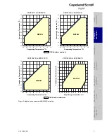
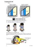
ZPD34K*E to ZPD91K*E ZPD103K*E to ZPD182K*E
ZRD42K*E to ZRD81K*E ZRD94K*E & ZRD125K*E
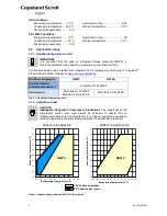
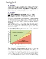
Figure 7: Recommended capacity modulation ranges according to the operating conditions
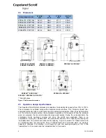
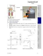
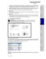
2.6 Mechanical differences in the Digital compressor ranges
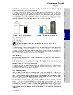
Figure 8: Single Digital Scrolls in the ZRD and ZPD ranges
The internal mechanics of the smaller and the larger models are different but functionally both
approaches to modulation achieve the same results and are to be controlled in exactly the same
way.
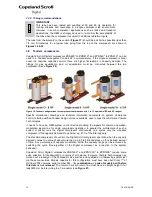
Figure 9: Modulation method in larger model ranges
25
30
35
40
45
50
55
60
65
70
-25
-20
-15
-10
-5
0
5
10
15
Con
dens
ing T
e
mpe
ra
tu
re
(
o
C)
Evaporating Temperature (
o
C)
R410A
Solenoid valve opens
10-100% recommended application range
50-100% recommended application range
75-100% recommended application range
Unloading floating seal
5
10
15
20
25
30
35
40
45
50
55
60
65
70
-25
-20
-15
-10
-5
0
5
10
15
Con
dens
ing T
e
mpe
ra
tu
re
(
o
C)
Evaporating Temperature (
o
C)
R410A


