C6.2.15/0815/E
21
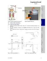
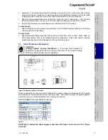
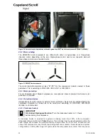
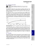
Figure 32: Crankcase heater location
excessive start up clearing noise. The addition of a crankcase heater will reduce noise and
dimming light complaints since the compressor will no longer have to clear out liquid during start.
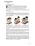
A crankcase heater is required for three-phase compressors when the system charge exceeds
the compressor charge limit listed in
Table 4
below.
Compressors
Refrigerant charge limit
ZRD42K* to ZRD81K* / ZPD34K* to ZPD91K*
4.5 kg
ZRD94K* & ZRD125K* / ZPD103K* to ZPD182K*
7.7 kg
Table 4
Practically, for a multi evaporator system, the
system charge will be much higher than for
standard single evaporator systems. In order to
prevent flooded start, we strongly recommend
that all
Digital Scroll
applications use a
crankcase heater.
The crankcase heater must be turned on a
minimum of 12 hours prior to starting the
compressor and must remain energised during
compressor off cycles.
The crankcase heater must be mounted below the oil Schraeder valve located on the bottom
shell (see
Figure 34
).
The crankcase heater should be wired in such a way that it is turned on whenever the
compressor is switched off.
4.3 Pressure safety controls
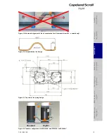
4.3.1 IPR valve (Internal Pressure Relief valve)
The internal pressure relief valves for models ZRD42K* to ZRD81K* and ZPD34K* to ZPD91K*
are located between the high and low sides of the compressor. They are designed to open when
the discharge-to-suction differential pressure exceeds 26-31 bar. When the valve opens, hot
discharge gas is routed back into the area of the motor protector to cause a trip. During
developmental blocked fan testing, it is sometimes noted that the valve opens, but the
compressor does not shut off while the discharge pressure continues to climb. This condition is
normally caused by floodback and may be corrected by using a more restrictive expansion
device or reducing the refrigerant charge.
Compressors ZRD94K*, ZRD125K* and ZPD120K* to ZPD182K* do not have internal pressure
relief valves. To ensure safe operation, a high-pressure control must be used in all applications
with these compressors.
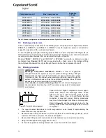
The high-pressure control should have a manual reset feature for the highest level of system
protection. Recommended cut-out setting for R407C is 29.5 bar, 45 bar for R410A. This
pressure control will act independently from the digital controller.
4.3.2 High-pressure control
A high-pressure control with a maximum cut-out setting of 30 bar(g) for ZRD models or 45 bar(g)
for ZPD models respectively is recommended.
The high-pressure cut-out should have a manual reset feature for the highest level of system
protection.
4.3.3 Low-pressure control
IMPORTANT
Loss of system charge! Loss of lubrication! Bearing malfunction and
compressor breakdown!
A low-pressure control is highly recommended for
loss of charge protection. Do not bridge or by-pass the low-pressure limiter.
Heat pumps in some geographical areas have to operate at low evaporating pressure because
of the low ambient temperatures, sometimes combined with a high level of relative humidity.
Good evaporator sizing and adequate defrost strategy control should prevent the system from
S
afet
y
in
struct
ion
s
P
ro
d
u
ct
d
es
cr
ipt
ion
Inst
all
atio
n
E
lec
tr
ica
l
c
o
n
n
ec
tion
S
tar
ting
up
&
o
p
er
atio
n
Ma
int
enan
c
e &
repai
r
Dismant
ling
&
d
ispo
sa
l

