Non-Overhaul Removal and Replacement
Teledyne Continental Motors, Inc.
TM
10-82
IOF-240 Series Engine Maintenance Manual
Change 1
31 August 2007
7.
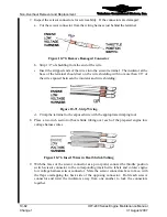
Inspect the scissor connectors for serviceability. If the connectors are damaged:
a.
Cut the scissor connector from the wiring harness just behind the terminal.
Figure 10-70.
Remove Damaged Connector
b.
Strip 1/2” of shielding from the end of the wire.
c.
Insert the stripped ends of the wires into the scissor terminal. The insulator at the
base of the terminal should rest on the wire shielding with no more than 1/8” of
the wire exposed between the insulator and wire shielding.
Figure 10-71.
Strip Wiring
d.
Crimp the terminal to the exposed wire with the appropriate crimping tool.
8.
Place a two inch section of heat shrink tubing over each of the prepared engine low
voltage harness wires.
Figure 10-72.
Insert Wires in Heat Shrink Tubing
9.
With the faces of the scissor connector as a pivot point, connect the throttle position
switch scissor connector to the corresponding (match wire labels and colors) engine
low voltage harness scissor connector. Mate the scissor connectors face to face, with
the flaps overlapping the back side of the opposing connector. Hold each scissor
connector and twist the insulators away from one another to lock the connectors
together.


