Teledyne Continental Motors, Inc.
TM
Non-Overhaul Removal and Replacement
IOF-240 Series Engine Maintenance Manual
10-79
31 August 2007
Change 1
3.
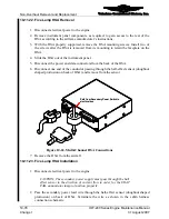
Connect the P9 and J10 connectors to the HSA.
4.
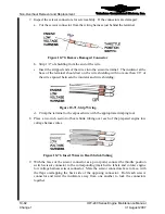
Slide the HSA into its instrument panel mounting location.
5.
While supporting the HSA, re-install the four HSA mounting screws.
6.
Use cable ties to secure the cabin harness as required.
7.
Re-assemble the instrument panel according to the airframe manufacturer’s
instructions.
8.
Restore electrical power to the engine.
9.
Perform a “FADEC Level I Diagnostics” (Chapter 8, Troubleshooting).
10-11.24. Two Lamp HSA Removal
Procedure
The two lamp HSA driver is mounted in the airframe according to airframe
manufacturer’s instructions. Consult the airframe manufacturer’s instructions for location
and removal instructions.
10-11.25. Two Lamp HSA Installation
Procedure
1.
Install the connector on the HSA driver and secure with two screws.
2.
Install the lamp driver in the airframe according to the airframe manufacturer’s
instructions.
3.
Perform FADEC Level I Diagnostic (Chapter 8) to verify lamp operation.
10-11.26. EDI Replacement
The airframe manufacturer determines the installed location of the optional EDI. Refer to
the airframe manufacturer’s instructions for EDI replacement.
10-11.27. Backup Battery Removal and Installation
The Backup battery must be replaced under the following conditions:
•
During Annual Inspection
•
If the backup battery has operated for one hour or more due to primary power failure
•
If the EBAT fail lamp remains illuminated for more than 5 minutes
Battery installation instructions are dependent upon airframe make and model. Refer to
applicable airframe manufacturer’s instructions for battery location and removal and
installation instructions.


