5. Using the Memory Address Map
48
ADI16-4(FIT)GY
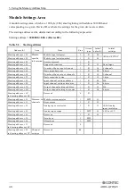
Module Settings Area
A module settings area, which is a 128-byte (80h) area beginning with address 301000h and
corresponding to a given Device ID, is where the settings for the given device are written.
The starting address can be determined according to the following expression:
Starting address
= 3 80h x (Device ID)
Table 5.1. Starting address
Address (h)
Area
Item
Size
Access
type
Initial
value (h)
Initial
settings
Starting a 00
Module-
specific
information
Module type (category)
1
R
02
ADI16-4(FIT)GY
Starting a 01
Module type (serial number)
1
R
02
Starting a 02
System-reserved
1
R
Starting a 03
Supported functions
1
R
01
Basic Input
Starting a 04
Number of basic input channels
1
R
04
4 channels
Starting a 05
Basic input data size
1
R
02
2 bytes
Starting a 06
Number of basic output channels
1
R
00
0 channel
Starting a 07
Basic output data size
1
R
00
0 byte
Starting a 08
Input channel settings address
1
R
20
20h
Starting a 09
Input channel settings data size
1
R
06
6 bytes
Starting a 0A
Output channel settings address
1
R
50
50h
Starting a 0B
Output channel settings data size
1
R
06
6 bytes
Starting a 0C
to Starting a 0F
Reserved
4
R
Starting a 10
Common to
channels
Module startup register
1
R/W
00
Starting a 11
Error status
1
R
00
Starting a 12
Analog input resolution
1
R
10
16-bit Analog
input resolution
Starting a 13
Analog input range
1
R/W
00
-10V to +10V
Starting a 14
Reserved
1
R
00
Starting a 15
Gain data
1
R/W
Starting a 16
Offset data
1
R/W
Starting a 17
to Starting a 1F
Reserved
9
Starting a 20
to Starting a 7F
Channel
settings
Reserved
96

