4. Using the I/O Address Map
30
ADI16-4(FIT)GY
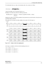
Starting a sampling process
If the sampling mode is the single-channel mode, specify the channel through which data is to be
converted.
In the case of the multi-channel mode, specify the upper limit (1 or greater) on the channels through
which data is to be converted.
Example: Specifying "3ch" results in the sampling of channels 0 to 3ch.
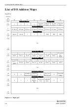
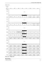
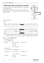
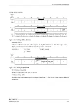
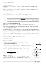
The control port for commencing a sampling process assumes the following state:
Starting
I/O
address
D7
D6
D5
D4
D3
D2
D1
D0
Output
Channel Data
+18
(12h)
0
0
0
0
0
0
Channel
Data1
Channel
Data0
Figure 4.20. Starting the sampling process
If the sampling mode is the software command, the specified channel is sampled only once.
In the case of an internal sampling clock, the internal sampling clock starts simultaneously with the
commencement of the first sampling.
If a sampling process is started with the sampling mode set to the clock mode, and then the sampling
process is restarted, any conversion data that has accumulated up to that point and the analog input status
are reset, and a new sampling operation is started.
The sampling stops when the module initialization command or the sampling condition-setting command
is executed.
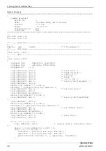
Following are examples in which a sampling process is started :
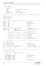
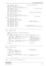
outp( ADR+18, 0x3 );
Input of conversion data
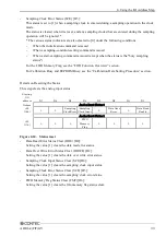
Conversion data should be input only after a verification is made that
conversion data is stored in a register.
Conversion data cannot be input from a register during a conversion operation.
The figure on the right shows procedures by which conversion data is input.
Conversion data is in the offset binary form. The relationship between
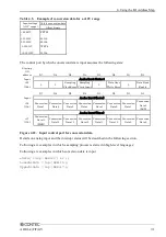
conversion data and input voltages is indicated by the following expression:
(V Offset )
Span
Data =
×2
12
Table 4.4. Input range
Input range
Offset
Span
Input range
Offset
Span
-10V to +10V
10
20
0mA to 20mA
0
20
Yes
Input data
Check DRE
status?
Start
Analog input status
End
Figure 4.21 Conversion data input
procedures

