4. Using the I/O Address Map
28
ADI16-4(FIT)GY
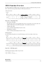
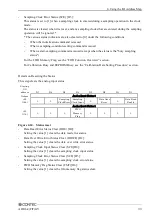
Setting the FIFO flag
The following example sets the FIFO memory flag status when FIFO memory stores 32 words of data.
For details, see the “FIFO Function Overview” section.
outp( ADR+24, 0x7 );
outp( ADR+28, 32 );
Input range-setting
The input range refers to the voltage range in which analog signals are input.
All channels are set on a common basis, and the input data is converted into digital signals with a 16-
bit resolution.
The input range is set by the DIP-switch and range data.
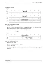
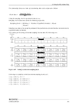
The input range-setting control port assumes the following state:
Starting
I/O
address
D7
D6
D5
D4
D3
D2
D1
D0
Output
Command
+24
(18h)
0
0
0
0
0
0
1
1
D7
D6
D5
D4
D3
D2
D1
D0
Output
Range Data
+28
(1Ch)
Range
Data7
Range
Data6
Range
Data5
Range
Data4
Range
Data3
Range
Data2
Range
Data1
Range
Data0
Figure 4.18. Setting an input range
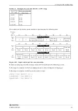
Table 4.3. Input range and settings data
Range
Input range
00h
±
10V
01 to BFh
Not decide
C0h
0 to 20mA
C1h and above
Not decide
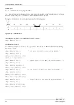
Following are examples in which an input range is set. The input range is set to -10 to 10V.
outp( ADR+24, 0x3 );
outp( ADR+28, 0x0 );
Setting an Internal Sampling Clock
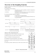
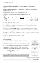
When either the "clock mode" or the "internal sampling clock" is selected as a sampling condition, this
option allows you to set a sampling cycle (clock data). In the initial state, the clock data is undefined.
Clock data must be set when an internal sampling clock is used.
Clock data is set in 250-nsec increments.
The allowable range is 10, 000nsec to 1, 073, 741, 824, 000nsec (approximately 17 minutes and 54
seconds), which corresponds to the setting data 39 to 4, 294, 967, 295.


