4. Using the I/O Address Map
ADI16-4(FIT)GY
33
-
Sampling Clock Error Status (SCE) [D5]:
This status is set to [1] when a sampling clock in entered during a sampling operation in the clock
mode.
The status is cleared when it is reset, and any sampling clocks that are entered during the sampling
operation will be ignored. *
* The various status indicators are also cleared to [0] under the following conditions:
-
When the initialization command is issued
-
When a sampling-condition-setting command is issued
-
When a start-sampling command is issued (except when the status is the "busy sampling
status")
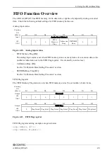
For the FIFO Memory Flag, see the “FIFO Function Overview” section.
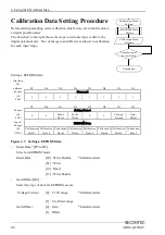
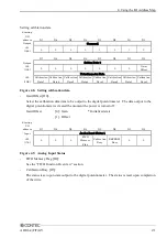
For Calibration Busy and EEPROM Busy, see the “Calibration Data Setting Procedure” section.
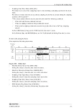
Details on Resetting the Status
This step clears the analog input status.
Starting
I/O
address
D7
D6
D5
D4
D3
D2
D1
D0
Output
Analog Input Status 0
+22
(16h)
0
0
Sampling
Clock Error
Sampling
Clock Input
0
Data Over
Error
0
Data Read
Enable
Analog Input Status 1
+23
(17h)
0
0
0
FIFO
Memory
Flag
0
0
0
0
Figure 4.24. Status reset
-
Data Read Error Status Clear (DRE) [D0]:
Setting the value [1] clears the data read error status.
-
Data Over Write Error Status Clear (DOWE) [D2]:
Setting the value [1] clears the data over write error status.
-
Sampling Clock Input Status Clear (SCI) [D4]:
Setting the value [1] clears the sampling clock input status.
-
Sampling Clock Error Status Clear (SCE) [D5]:
Setting the value [1] clears the sampling clock error status.
-
FIFO Memory Flag Status Clear (FMF)[D4]:
Setting the value [1] clears the fifo memory flag status clear.


