


3. External Connection
ADA16-32/2(PCI)F
33
Differential Input
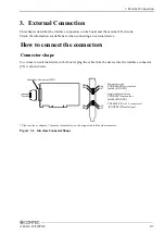
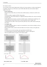
The following figure shows an example of flat cable connection.
For each analog input channel on CN1, connect the "+" input to the signal and connect the "-" input to
the signal source ground. Also connect the analog ground on the board to the signal source ground.
Analog Input 0[+]..15[+]
Analog Ground
BOARD
Cable
Signal Source
Analog Input 0[-]..15[-]
CN1
Figure 3.5. Differential Input Connection (Flat Cable)
The following figure shows an example of shielded cable connection. Use shielded cable if the
distance between the signal source and board is long or if you want to provide better protection from
noise. For each analog input channel on CN1, connect the "+" input to the signal and connect the "-"
input to the signal source ground. Also connect the analog ground on the board and the signal source
ground to the shielding.
Analog Input 0[+]..15[+]
Analog Ground
BOARD
Signal Source
Analog Input 0[-]..15[-]
CN1
Shield cable
Figure 3.6. Differential Input Connection (Shield Cable)
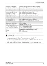
CAUTION
-
If the signal source contains over 1MHz signals, the signal may effect the cross-talk noise between
channels.
-
When the analog ground is not connected, the conversion data is not determined.
-
If the board and the signal source receive noise or the distance between the board and the signal
source is too long, data may not be input properly.
-
An input analog signal should not exceed the maximum input voltage (relate to the board analog
ground). If it exceeds the maximum voltage, the board may be damaged.
-
Connect all the unused analog input channels to analog ground.
-
In the channel switching, the multiplexer does the electrical charge and discharge on the internal
capacitor according to the signal voltage. Therefore, the voltage from the previous switching state
may go into the next channel. It might cause the error of the signal source action. If this occurs,
insert a high-speed amplifier as a buffer between the signal source and the analog input pin to
reduce the fluctuation.
-
An input pin may fail to obtain input data normally when the signal source connected to the pin has
high impedance. If this is the case, change the signal source to one with lower output impedance
or insert a high-speed amplifier buffer between the signal source and the analog input pin to reduce
the effect.
Содержание ADA16-32/2(PCI)F
Страница 1: ...PC HELPER High Resolution Speed Analog I O Board for PCI ADA16 32 2 PCI F User s Guide CONTEC CO LTD ...
Страница 7: ...vi ADA16 32 2 PCI F ...
Страница 33: ...2 Setup 26 ADA16 32 2 PCI F ...
Страница 45: ...3 External Connection 38 ADA16 32 2 PCI F ...
Страница 99: ...5 About Software 92 ADA16 32 2 PCI F ...
Страница 108: ......