background image

28

COMUNELLO

  ®Copyright 2016 - All rights reserved

CONTENTS

1  

GENERAL PRESCRIPTIONS

1.1 

Safety prescriptions

1.2 

Installation prescriptions

1.3 

Operating prescriptions

MODELS AND PRODUCT DESCRIPTION

2.1 Description
2.2 

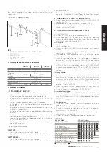
Typical installation

PRODUCT TECHNICAL SPECIFICATIONS

4 INSTALLATION 

4.1 

Preliminary checks  

4.2 

Operating limits  

4.3 

Preparatory work for installation  

4.4 

Installing the LIMIT barrier system  

4.4.1 Installation
4.4.2  Limit stops adjustment 
4.4.3  Manual release 

PREPARATION FOR ELECTRICAL CONNECTIONS

6 TESTING

PRODUCT MAINTENANCE

SPARE PARTS

DISPOSAL OF THE PRODUCT

10 

ELECTRONIC CIRCUIT BOARD

10.1   Technical characteristics
10.2  Electrical connections
10.3   Functional characteristics
10.4   Programming

11


WARRANTY

1 GENERAL PRESCRIPTIONS

1.1 SAFETY PRESCRIPTIONS

This installation manual is addressed exclusively 

to professionally skilled personnel. Read all the 

instructions carefully before starting the installation 

procedures. Any operations that are not expressly 

set down in these instructions are to be considered 

prohibited; improper use may result in damage to 

the product and place persons and property at risk. 

The manufacturer declines all liability for failure to 

observe best technical practices in barrier system 

construction and for any possible deformations 

that may occur when using the product. Store 

this manual in a safe place for future reference. 

The design and construction of the devices 

fitted on the LIMIT model as well as this manual 

are in full compliance with statutory legislation. In 

consideration of potential hazards that may arise 

during the installation and use of LIMIT, also the 

installation procedures must be carried out in full 

compliance with the applicable laws, standards 

and regulations; specifically:

1.2 INSTALLATION PRESCRIPTIONS

• Before starting the installation procedures 

make sure you have any additional devices 

and materials that may be required to complete 

the LIMIT barrier system in consideration of the 

specific application.

• The automation system must not be used until 

the transit area has been made safe.

• Dispose of packaging materials in compliance 

with local regulations.

1.3 OPERATING PRESCRIPTIONS

• No modifications can be made to any part of the 

product unless

specified in this manual. Unauthorized modifications 

of the product are likely to lead to malfunctions. 

The manufacturer declines all liability for damage 

caused by unauthorized modifications.

• The parts of the automation system must never 

be immersed in water or other liquids. During 

the installation procedures ensure that no solid 

objects or liquids penetrate inside the control 

unit or other open devices.

• If liquids penetrate any parts of the automation 

system, disconnect the electrical power supply 

immediately and consult technical service; the 

use of LIMIT in such conditions may give rise to 

potentially hazardous situations.

• Keep all parts of the LIMIT barrier system away 

from heat sources and open flames; exposure 

to heat or flames may damage the devices and 

cause faults, fire, or hazardous situations.

• When the system remains unused for a long 

time, remove the optional battery and store it in 

a dry place to avoid the risk of leakage of harmful 

substances.

• Connect the control unit exclusively to an electric 

power supply line equipped with an efficient 

protective earth conductor.

• Any operations that require parts of the LIMIT 

barrier system to be opened must be performed 

with the control unit and the electrical power 

supply disconnected; if the disconnect device 

is not clearly visible from where you are working, 

attach a warning notice to the effect:  “WARNING 

- MAINTENANCE IN PROGRESS”.

• In the case of tripping of circuit breakers or 

blowing of fuses, find the fault and remedy it 

before resetting the circuit breaker or changing 

the fuse.

• If the fault cannot be remedied using the 

information given in this manual, consult technical 

service. 

• The device can’t be used by children younger 

than 8 years of age and by people with reduced 

physical, sensory or mental capabilities, or 

without experience or the required knowledge if 

not under surveillance or after having received 

instructions about the safe use of the device 

and the inherent risks in it. Children should not 

play with the device. Cleaning and maintenance 

should not be carried out by children without 

surveillance.

• Children can’t play with the commands of the 

automatism. Remote controls should be kept 

out of reach of children. It is suggested to 

periodically examine the installation in order 

to verify the presence of possible damages 

to the cables, springs and mechanical parts. 

Automation should not be used if it is necessary 

a repair intervention.

2  MODELS AND PRODUCTS DESCRIPTION

2.1 DESCRIPTION 

Sturdy and easy to install, the LIMIT electromechanical barrier system is 

Содержание LIMIT 500

Страница 1: ...S MANUAL Electromechanical road barrier system ISTRUZIONI D USO E DI INSTALLAZIONE INSTALLATIONS UND GEBRAUCHSANLEITUNG INSTRUCIONS D UTILISATION ET D INSTALLATION INSTRUCCIONES DE USO Y DE INSTALACIO...

Страница 2: ...2 COMUNELLO Copyright 2016 All rights reserved FIG 1A FIG 1B FIG 1C 1170 815 320 220 301 1185 838 420 250 333 1185 838 420 250 333 LIMIT 800 LIMIT 600 LIMIT 500...

Страница 3: ...3 COMUNELLO Copyright 2016 All rights reserved FIG 2A FIG 2B FIG 3 FIG 4 FIG 3B FIG 5...

Страница 4: ...4 COMUNELLO Copyright 2016 All rights reserved FIG 6B FIG 6A Add screws with threadlocker glue Add screws with threadlocker glue...

Страница 5: ...5 COMUNELLO Copyright 2016 All rights reserved FIG 7A FIG 7B FIG 8A FIG 8C FIG 8B FIG 9A...

Страница 6: ...6 COMUNELLO Copyright 2016 All rights reserved FIG 9B FIG 9C FIG 10A FIG 11A FIG 12 FIG 11B FIG 11C FIG 11D...

Страница 7: ...7 COMUNELLO Copyright 2016 All rights reserved FIG 13A FIG 13B FIG 14A FIG 14B...

Страница 8: ...8 COMUNELLO Copyright 2016 All rights reserved FIG 16A FIG 16B FIG 15...

Страница 9: ...9 COMUNELLO Copyright 2016 All rights reserved FIG 17 FIG 18A FIG 18B...

Страница 10: ...10 COMUNELLO Copyright 2016 All rights reserved DEFLECTOR FIXING FIG 20A...

Страница 11: ...11 COMUNELLO Copyright 2016 All rights reserved CLIP LED FIXING TO AVOID INTERFERENCES WITH COMPONENTS FIG 20B...

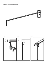
Страница 12: ...12 COMUNELLO Copyright 2016 All rights reserved LIMIT 500 SWING DOWN SUPPORT 45 MIN FIG A FIG C FIG B...

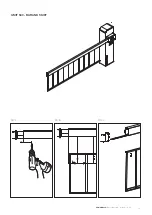
Страница 13: ...13 COMUNELLO Copyright 2016 All rights reserved LIMIT 600 SWING DOWN SUPPORT 45 MIN FIG A FIG C FIG B...

Страница 14: ...LIMIT 800 SWING DOWN SUPPORT 45 MIN FIG A FIG C FIG B...

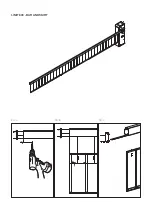
Страница 15: ...15 COMUNELLO Copyright 2016 All rights reserved LIMIT 500 BAR AND SKIRT FIG A FIG C FIG B 110 MIN 110 MIN 200 200...

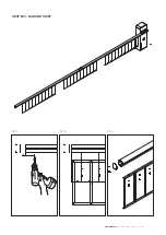
Страница 16: ...LIMIT 600 BAR AND SKIRT FIG A FIG C FIG B 110 MIN 110 MIN 200 200...

Страница 17: ...17 COMUNELLO Copyright 2016 All rights reserved LIMIT 800 BAR AND SKIRT FIG A FIG C FIG B 110 MIN 110 200 200...

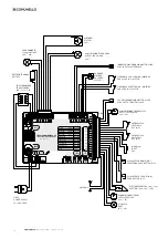
Страница 18: ...MOTORE 1 MOTOR 1 24V FINECORSA APERTURA N C MOTORE END OPEN N C MOTOR FINECORSA CHIUSURA N C MOTORE END CLOSE N C MOTOR ENCODER MOTORE 1 ENCODER MOTOR 1 ALIMENTAZIONE FOTOCELLULE PHOTOCELL POWER 24V...

Страница 19: ...sposizioni legislative che traspongono le seguenti direttive 2014 30 EU Direttiva EMCD 2011 65 EU Direttiva RoHS 2006 42 CE Direttiva MD 1999 5 CE Direttiva R TTE e che sono state applicate tutte le n...

Страница 20: ...ponsabilit per danni derivati da prodotti modificati Evitare che le parti dell automatismo possano venir immerse in acqua o in altre sostanze liquide Anche durante l installazione evitare che parti so...

Страница 21: ...di passaggio cavi Fissarla con i dadi e rondelle in dotazione FIG 5 Assemblaggio asta Per comporre un asta di 7 o 8 metri necessario assemblare 2 pezzi tra i disponibili di lunghezza 3 4 5 metri Nel...

Страница 22: ...e assicuri la disconnessione completa onnipolare dalla rete con categoria III di sovratensione e con una distanza di apertura dei contatti in ciascun polo di almeno 3 mm conformemente alle regole di i...

Страница 23: ...ne della Forza Motore durante il ciclo rallentato La regolazione pu essere effettuata con un range da 50 al 100 della Forza massima durante il ciclo Rallentato RILEVAMENTO OSTACOLO La centrale elettro...

Страница 24: ...clo Normale di Apertura La centrale permette di definire diversi profili Forza motore durante il ciclo di funzionamento Normale in fase di Apertura Nella configurazione fornita dal costruttore Forza d...

Страница 25: ...econdi di tempo per selezionare le funzioni del Men Esteso 2 mediante l uso dei tasti SEL e SET trascorsi ulteriori 30 secondi la centrale ritorna al men principale LED SPENTO LEDACCESO L1 EL SERR BLO...

Страница 26: ...fabbricazione Fratelli Comunello S p a garantisce in via esclusiva e quindi con esclusione di domande risarcitorie formulate per equivalente la riparazione o sostituzione gratuita delle parti difettos...

Страница 27: ...set down in the following directives 2014 30 EU EMCD Directive 2011 65 EU RoHS Directive 2006 42 CE MD Directive 1999 5 CE R TTE Directive and that all the rules and or technical specifications shown...

Страница 28: ...ons of the product are likely to lead to malfunctions The manufacturer declines all liability for damage caused by unauthorized modifications The parts of the automation system must never be immersed...

Страница 29: ...through the cable inlet hole Secure the pedestal with the nuts and washers supplied FIG 5 Arm assembly To create an arm of 7 or 8 metres long assemble 2 sections available in 3 4 5 metre lengths When...

Страница 30: ...electrical grid with the 3rd category of overvoltage and with an opening distance of the contacts in each pole of at least 3 mm in compliance with the installation rules and directly connected to the...

Страница 31: ...E The electronic control unit is equipped with a SLOWING trimmer adjustment of Motor Force during the Slowdown cycle Adjustment can be performed in a range of between 50 and 100 of maximum force durin...

Страница 32: ...Normal operating cycle in the Opening movement In the factory set configuration operator Force during opening is set at the maximum level MAX i e identical to the setting selected using the SPEED trim...

Страница 33: ...you wish to enable the Arm clamp function proceed as follows ensure you have enabled Extended Menu 2 alternate blinking 1 1 0 1 1 0 1 1 0 of menu level no 8 and then use the SEL key to select blinkin...

Страница 34: ...rial found to be faulty and returned to Fratelli Comunello S p a shall remain property of the Seller Any cost resulting from any work needed to repair the defect or to replace the material shall be ch...

Страница 35: ...folgende Richtlinien umsetzen 2014 30 EU EMCD Richtlinie 2011 65 EU RoHS Richtlinie 2006 42 CE MD Richtlinie 1999 5 CE R TTE Richtlinie und dass alle folgenden Normen und oder technischen Spezifikati...

Страница 36: ...rten Produkten herf hren Es ist zu vermeiden dass Teile der Automatisierung in Wasser oder andere fl ssige Stoffe tauchen k nnen Auch w hrend der Installation ist zu vermeiden dass Feststoffe oder Fl...

Страница 37: ...hrankenheber mit den beigestellten Muttern und Scheiben befestigen ABB 5 Zusammenbau des Schrankenbaumes Um einen 7 oder 8 m langen Schrankenbaum zu bilden sind 2 Teile aus den verf gbaren L ngen von...

Страница 38: ...ang zum Versorgungsnetz der Automatisierung eine Vorrichtung einplanen die gem den Installationsregeln eine komplette allpolige Abschaltung vom Netz gew hrleistet mit berspannungskategorie III und ein...

Страница 39: ...serkennung notwendigen Gegenkraft ausgestattet die ganz vom Mikroprozessor gesteuert wird Die Einstellung kann mit einer Ansprechzeit zwischen mindestens 0 1 Sek und maximal 1 Sek erfolgen Achtung Das...

Страница 40: ...r LED NR4 stellen dann auf den Taster SET dr cken und im gleichen Moment schaltet die LED NR4 permanent ein und die Programmierung wird abgeschlossen Falls das Profil auf einen Mindestwert MIN ge nder...

Страница 41: ...das Hauptmen zur ck LEDAUSGESCHALTET LED EINGESCHALTET L1 EL SCHLOSS SPERRE ELEKTROSCHLOSS ELEKTROSPERRE L2 KONTR AUSG BLINKL BLINKLEUCHTE FESTLICHT L3 IMMER SCHLIESSEN OFF ON L4 FOLLOW ME OFF ON L5 V...

Страница 42: ...frei die fehlerhaften Teile die als fehlerhafte Teile laut dem unanfechtbarem Urteil des Fachpersonal von Fratelli Comunello S p A anerkannt werden Die Ausbesserung bzw Ersetzung ist die einzige Entsc...

Страница 43: ...aux dispositiones l gales transposant les directives suivantes 2014 30 EU Directive EMCD 2011 65 EU Directive RoHS 2006 42 CE Directive MD 1999 5 CE Directive R TTE Et qui ont t soumis toutes les norm...

Страница 44: ...dans ce manuel Ce type d intervention est uniquement susceptibled entra nerdesdysfonctionnements Le constructeur d cline toute responsabilit en cas de dommages entra n s par une modification du produ...

Страница 45: ...BARRI RE LEVANTE LIMIT 4 4 1 INSTALLATION Retirer le couvercle frontal au moyen de la cl fournie FIG 4 Poser la barri re levante sur la contre plaque en faisant passer les c bles d alimentation et des...

Страница 46: ...proximit des bornes et il doivent li s avec des manchons Pendant l installation utiliser exclusivement supports de cables en plastique Utiliser supports diff rents pour les c blages en basse tension 2...

Страница 47: ...ns de course ouverture et fermeture NF L intervention des phases de fonctionnement respectives provoque l arr t imm diat du mouvement R GLAGE PUISSANCE MOTEUR DURANT LE CYCLE NORMAL La logique lectron...

Страница 48: ...ppuyer nouveau rapidement sur la touche SET la m morisation du temps de fermeture automatique est effectu e et la LED L3 reste allum e fixe Pour r tablir la condition initiale sans fermeture automatiq...

Страница 49: ...ure de l automatisme R p ter l op ration pour r tablir la configuration initiale MENU COMPLET 2 La logique est fournie par le fabricant avec possibilit de s lection directe sur le menu principal uniqu...

Страница 50: ...st pr te l utilisation Cette pr caution permet une pr vention des pannes conforme la cat gorie 2 de l EN 954 1 GARANTIE Fratelli Comunello S p A garantie sous r serve de conformit avec les performance...

Страница 51: ...nforme a las disposiciones legales que transponen las seguientes directivas 2014 30 EU Directiva EMCD 2011 65 EU Directiva RoHS 2006 42 CE Directiva MD 1999 5 CE Directiva R TTE Y que han sido aplicad...

Страница 52: ...e manual Las operaciones de este tipo pueden provocar fallos de funcionamiento El fabricante declina toda responsabilidad por da os causados por productos modificados Evite que las piezas del automati...

Страница 53: ...la llave entregada FIG 4 Apoye el accionador de barrera en la contraplaca pasando los cables de alimentaci n y de los accesorios a trav s del orificio de paso de los cables F jela con las tuercas y ar...

Страница 54: ...n categoria III de sobretensi n y con una distancia de apertura de los contactos en cada polo por lo menos de 3 mm conformemente a las reglas de insalacci n y directamente colegado a los bornes de ali...

Страница 55: ...cuadro electr nico incorpora un trimmer SLOWING para la regulaci n de la Fuerza del Motor durante el ciclo Ralentizado La regulaci n se puede hacer dentro de un rango desde 50 a 100 de la Fuerza m xi...

Страница 56: ...e el ciclo de funcionamiento Normal en la fase de Apertura En la configuraci n suministrada por el fabricante la Fuerza del motor en la fase de Apertura est ajustada con el valor m ximo M X es decir q...

Страница 57: ...zar a destellar de manera alternada 1 1 0 1 1 0 De esta manera usted tendr 30 segundos de tiempo para seleccionar las funciones del Men Ampliado 2 mediante el uso de los pulsadores SEL y SET transcurr...

Страница 58: ...i n al cumplimiento de las especicaciones de rendimiento que guran en los manuales de instrucciones de los productos el buen funcionamiento de los actuadores durante 24 meses desde la fecha de fabrica...

Страница 59: ...02 CE COMUNELLO LUCA F lli COMUNELLO spa Via Cassola 64 36027 Ros VI Italy LIMIT 500 LIMIT 600 LIMIT 800 2014 30 EU D 2011 65 EU RoHS 2006 42 CE MD 1999 5 CE R TTE EN61000 6 2 2005 EN61000 6 3 2007 E...

Страница 60: ...LLO Copyright 2016 All rights reserved 1 1 1 1 2 1 3 2 2 1 2 2 3 4 4 1 4 2 4 3 4 4 LIMIT 4 4 1 4 4 2 4 4 3 5 6 7 8 9 10 10 1 10 2 10 3 10 4 1 1 1 LIMIT LIMIT 1 2 LIMIT 1 3 Comunello LIMIT LIMIT LIMIT...

Страница 61: ...0 24 150 6 5 A 100 300 15 ON 45 OFF IP 24 D II 2 20 50 C 65 65 95 4 4 1 1A 1 B 1C 4 2 LIMIT 500 3 4 LIMIT 600 800 3 7 LIMIT 500 600 800 4 3 2A LIMIT 500 2B LIMIT 600 800 3A 4 3 4 4 LIMIT 4 4 1 4 5 7 8...

Страница 62: ...dium spring AC 540 LIMIT 600 BAR ASSEMBLY LENGTH meters AND SPRING CHOICE 2 0 2 5 3 0 3 5 4 0 4 5 5 0 5 5 6 0 Bar Bar with bar cover kit Bar with bar cover kit and led Bar with swing down support Bar...

Страница 63: ...0 LED 24V LED 50 CN2 SYNC Master Slave SYNC Master Slave FOTO 24 3 FOTO GND DS2 2 NC GND GND DS1 1 NC STOP 8K2 NC GND GND P PED PED NA PP NA ELS 24 10 24 ELS 24 10 GND 24V 5W 24 5 GND GND 24VLED 24 4...

Страница 64: ...8 00 18 00 27 4 3 12 4 MASTER SLAVE Dip Switch SW1 Switch SW1 DIP 1 DIP 2 Switch SW1 Master Slave Master Slave PUL PED Slave Master INV 1 ON 2 OFF MASTER INV ON SLAVE 1 ON 2 SW1 SW1 10 4 SEL 10 SET SE...

Страница 65: ...4 SET LED L4 MIN SEL L4 5 MAX SPEED LED L5 MED SEL LED L5 SET LED L5 MIN SEL L5 6 MAX SLOWING LED L6 MED SEL LED L6 SET LED L6 MIN SEL L6 7 MAX SLOWING LED L7 MED SEL LED L7 SET LED L7 MIN SEL 7 1 1 8...

Страница 66: ...1 1 0 1 0 1 8 SEL 4 SET LED L4 5 6 7 8k2 NC 8 CN2 8 2 1 1 0 1 0 1 0 8 SEL 7 SET LED L7 2 2 8 2 SET 1 1 0 1 1 0 30 2 SEL SET 30 L1 L2 L3 L4 L5 L6 1 L7 2 LEV 2 2 8 2 SET 1 1 0 1 1 0 30 2 SEL SET 30 1 2...

Страница 67: ...0 8 SEL 5 SET LED L5 3 6 1 24 50 LED 2 1 1 0 1 1 0 8 SEL 6 SET LED L6 7 2 24 50 2 1 1 0 1 1 0 8 SEL 7 SET LED L7 SEL SET 5 1 1 6 EN 12453 2 EN 954 1 Fratelli Comunello S p a 24 Fratelli Comunello S p...

Страница 68: ...NOTES...

Страница 69: ...69 COMUNELLO Copyright 2016 All rights reserved NOTES...

Страница 70: ...NOTES...

Страница 71: ...71 COMUNELLO Copyright 2016 All rights reserved NOTES...

Страница 72: ...FRATELLI COMUNELLO S P A AUTOMATION GATE DIVISION Via Cassola 64 C P 79 36027 Ros Vicenza Italy Tel 39 0424 585111 Fax 39 0424 533417 info comunello it www comunello com...

Отзывы: