Compaq Deskpro 2000 Series Скачать руководство пользователя страница 183

5-70

Removal and Replacement Procedures

5.2.9

Expansion Board Guide

To remove the expansion board guide from the minitower computer, complete the following steps:

 1.  Perform preparation procedures described in Section 5.2.3.

  2.  Remove the access panel (Section 5.2.6.1).

  3.  Remove the expansion brace (section 5.2.7).

  4.  Remove the expansion boards (Section 5.2.8).

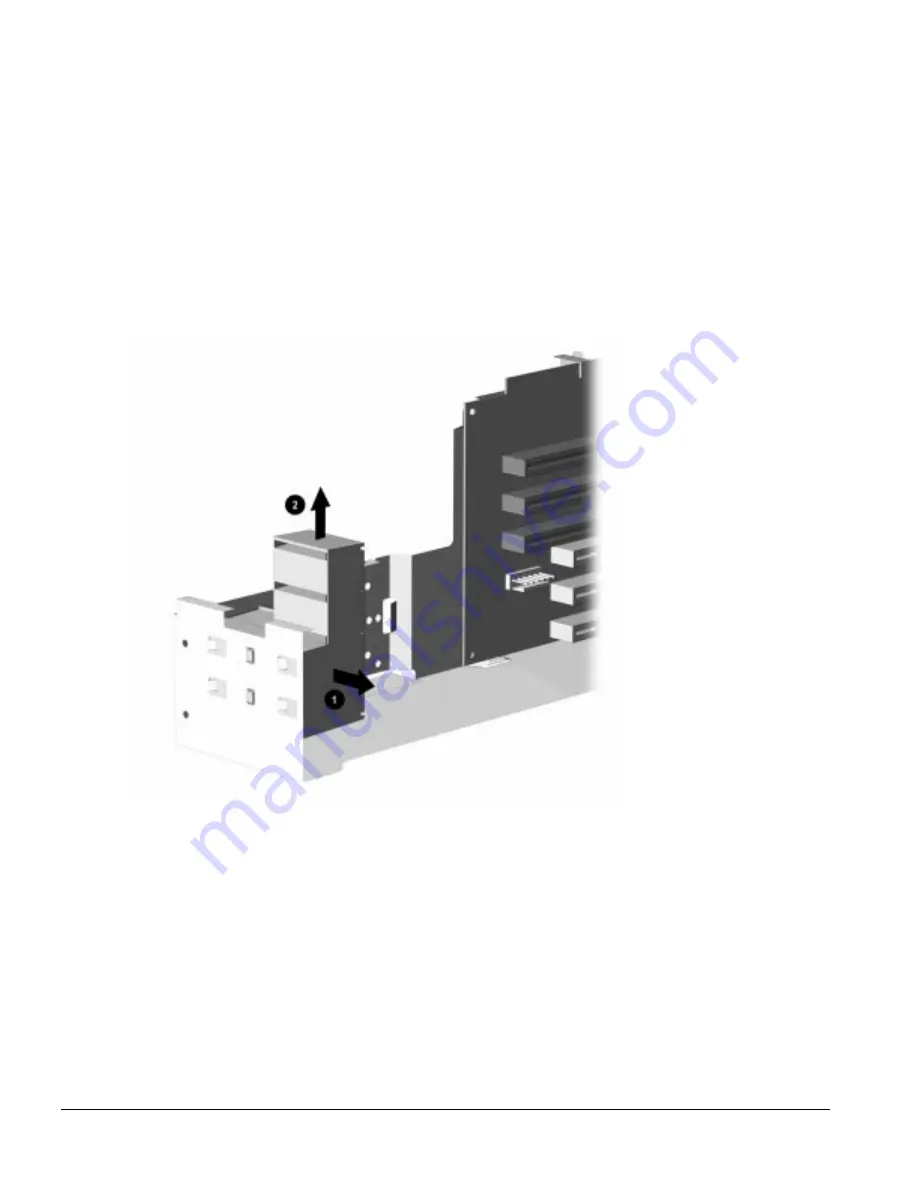
  5.  Slide the board guide to the right and unsnap it from the front of the chassis.

Figure 5-65.

  Removing the Minitower Expansion Board Guide

To replace the expansion board guide, reverse the above procedure.

Содержание Deskpro 2000 Series

Страница 1: ...MAINTENANCE SERVICE GUIDE COMPAQ DESKPRO 2000 SERIES OF PERSONAL COMPUTERS...

Страница 2: ...243064 001 243211 001...

Страница 3: ...ompaq Computer Corporation All rights reserved Printed in the U S A Compaq Deskpro Registered U S Patent and Trademark Office Microsoft MS DOS and Windows are registered trademarks of Microsoft Corpor...

Страница 4: ...CPS...

Страница 5: ...pheral Interface 1 8 1 3 8 System I O 1 8 1 3 9 System BIOS 1 9 PCI Auto Configuration 1 9 IDE Auto Configuration 1 9 ISA Plug and Play Capability 1 9 BIOS Upgrades 1 9 1 3 10 Expansion Slots 1 9 1 3...

Страница 6: ...3 1 Preparing the Computer 2 8 2 3 2 Accessing the Configuration and Diagnostics Menu 2 8 Accessing the Configuration and Diagnostics Menu at Startup 2 8 Accessing the Configuration and Diagnostics M...

Страница 7: ...vice Considerations 4 4 4 2 1 Tools and Software Requirements 4 4 4 2 2 Screws 4 4 4 2 3 Cables and Connectors 4 5 4 2 4 Hard Drives 4 5 4 2 5 Plastic Parts 4 5 4 2 6 Lithium Battery 4 5 chapter 5 Rem...

Страница 8: ...quence Chart 5 60 5 2 3 Preparation for Disassembly 5 61 5 2 4 Feet 5 62 5 2 5 Cable Lock 5 63 5 2 6 Exposing the Chassis 5 64 5 2 6 1 Access panel 5 64 5 2 6 2 Minitower J Hood 5 66 5 2 7 Riser Brace...

Страница 9: ...Settings 6 15 6 3 7 1 0 GB SCSI Hard Drive Jumper Settings 6 16 6 3 8 2 1 GB Ultra SCSI Hard Drive Jumper Settings 6 17 6 4 CD ROM Drive Jumper Settings 6 18 6 5 PD CD Drive Jumper Settings 6 18 chap...

Страница 10: ...ickBlank 7 13 7 4 2 Keyboard and Mouse Interface 7 15 Disabling the Keyboard and Mouse Interface 7 15 Enabling the Keyboard and Mouse Interface 7 15 7 5 Flash ROM 7 16 7 6 Intelligent Manageability 7...

Страница 11: ...loss of data Text set off in this manner presents clarifying information specific instructions commentary sidelights or other points of information The following format conventions distinguish element...

Страница 12: ...ance on the front and back of the computer WARNING The computer is designed to be electrically grounded To ensure proper operation plug the AC power cord into a properly grounded electrical outlet onl...

Страница 13: ...pro 2000 1 1 chapter 1 PRODUCT DESCRIPTION This chapter describes the model offerings and features of the Compaq Deskpro 2000 Series of Personal Computers Figure 1 1 Compaq Deskpro 2000 Series Persona...

Страница 14: ...0 1 08 GB No 8 MB 128 MB 256K Cirrus Logic HVS6 P5 120 1 08 GB No 16 MB 128 MB 256K Cirrus Logic HVT3 P5 133 1 2 GB No 16 MB 128 MB 256K Cirrus Logic HVT5 P5 133 2 5 GB No 16 MB 128 MB 256K Cirrus Log...

Страница 15: ...2 5 GB Yes 16 MB 128 MB 256K Cirrus Logic HVX7 P5 133 1 62 GB Yes 16 MB 128 MB 256K Cirrus Logic HVY6 P5 166 2 5 GB Yes 32 MB 128 MB 256K Cirrus Logic HVY7 P5 166 1 62 GB Yes 32 MB 128 MB 256K Cirrus...

Страница 16: ...xtended data out EDO dynamic random access memory DRAM standard expandable to 128 or 192 megabytes of DRAM installed in single inline memory modules SIMMs BIOS in a flash memory device supports PCI au...

Страница 17: ...graphic location 1 62 GB is the largest drive available in EMEA The 2 5 gigabyte hard drive is partitioned into two equally sized logical drives Drive fault prediction on all hard drives One 1 44 mega...

Страница 18: ...and five screws on the Pentium Pro to secure the system board to the chassis In addition the I O bracket is mounted to the system board and is spared that way The riser board mounts perpendicular to...

Страница 19: ...and FPM modules are combined in the computer they must be as matched pairs For example two identical EDO modules may be used with two identical FPM modules The SIMM sockets on all system boards in thi...

Страница 20: ...ers are listed in Chapter 8 Specifications 1 3 7 IDE Peripheral Interface The onboard PCI chipset provides a high speed 32 bit PCI IDE interface which supports the following Up to four PCI IDE hard dr...

Страница 21: ...configuration of Plug and Play ISA boards and resource management for legacy non Plug and Play ISA boards when used with Compaq s Computer Setup for Windows CSW utility or F10 Setup or a Plug and Pla...

Страница 22: ...ing and Chapter 7 Compaq Utilities 1 3 16 Keyboard Mouse Controller The onboard 8042 I O controller stores the keyboard and mouse controller code Connectors for the keyboard and mouse are located on t...

Страница 23: ...Safety Comfort Guide Intelligent Manageability Power Management with Energy Saver features Security Management Windows NT Workstation 3 51 The Windows NT 3 51 operating system software is provided on...

Страница 24: ...developments while the single CD ROM offers information as it is needed When calling Compaq to place an order be sure to have the serial number of the computer available The serial number is located...

Страница 25: ...physically secure the computer hardware to protect against theft Diskette boot control prevents the computer from being booted from a diskette Diskette drive control allows disabling of the diskette...

Страница 26: ...Lights Table 1 3 Lights and Controls Ref Component Function Diskette Drive Activity Light Turns on when the diskette drive is reading or writing Diskette Eject Button Ejects a loaded diskette Power Sw...

Страница 27: ...CD ROM drive half height 3 Optional diskette drive 5 25 inch or 3 5 inch tape drive hard drive or CD ROM drive half height 4 Primary hard drive bay 3 5 inch third height 5 Primary hard drive bay 5 25...

Страница 28: ...phics controller card NOTE The Matrox MGA Millennium graphics controller also includes a multimedia port 3 Power Cord Connection Connects the computer to an electrical power outlet 4 Universal Serial...

Страница 29: ...0 1 17 1 5 Minitower Computer Features The Compaq Deskpro 2000 Minitower Personal Computer comes with a mouse and keyboard You will also need a Compaq color monitor or other compatible monitor to oper...

Страница 30: ...1 18 Product Description 1 5 1 Front Panel Lights and Controls Figure 1 5 Power Switch and Front Panel Lights...

Страница 31: ...he diskette drive is reading or writing 8 Diskette Eject Button Ejects a loaded diskette 9 CD ROM Eject Button Opens and closes the CD ROM tray 10 CD ROM Emergency Eject Hole Manually ejects a CD if t...

Страница 32: ...1 20 Product Description Figure 1 6 Drive Positions on the Minitower Computer...

Страница 33: ...rive half height To verify the type size and capacity of the mass storage devices installed in the computer run Compaq Diagnostics in Windows or run the View System Information INSPECT utility availab...

Страница 34: ...1 22 Product Description Figure 1 7 Rear Panel Connectors...

Страница 35: ...l device such as a serial printer 4 Keyboard Connector Connects the keyboard 5 Mouse Connector Connects the mouse 6 Parallel Connector Connects a parallel device such as a parallel printer 7 Monitor C...

Страница 36: ...Explorer for example pressing F1 usually causes help information to appear on the screen 3 Windows Logo keys 4 Windows Application key 5 Arrow keys for moving the cursor up down right and left 6 Numer...

Страница 37: ...ific keyboard functions The corresponding lights at the top of the keyboard indicate whether the keyboard functions are on or off Num Lock Caps Lock and Scroll Lock The keyboard function is operating...

Страница 38: ...1 26 Product Description The keyboard has feet on the bottom that enable the user to tilt the keyboard to a more comfortable typing angle Figure 1 10 Keyboard Tilt Foot...

Страница 39: ...nts the screen from scrolling in some spreadsheet applications 6 Pause Temporarily suspends screen scrolling or some operations 7 Num Lock When the Num Lock light is on the numeric keypad is activated...

Страница 40: ...e Options The following mass storage options are available from Compaq for the Compaq Deskpro 2000 Series of Personal Computers Diskette drives 1 2 MB half height diskette drive LS 120 drive 1 44 120...

Страница 41: ...s controller 1 7 5 Serial Parallel Interface Board The serial parallel interface board option is available from Compaq for the Compaq Deskpro 2000 Series of Personal Computers This board uses an expan...

Страница 42: ...skpro 2000 Series of Personal Computers MS DOS 6 3 5 inch diskettes Corporate license agreements for MS DOS 6 MS DOS 6 LicensePaq MS DOS 6 corporate upgrade 100 users MS DOS 6 LicensePaq upgrade Netwa...

Страница 43: ...ice 2 1 Power On Password The power on password prevents use of the computer until the password is entered If the power on password is set a key icon appears on the screen when POST completes If this...

Страница 44: ...er off then move the jumper plug from pins 6 and 7 to pins 5 and 6 and restart the computer The password can then be reestablished through Security Management The E6 jumper location is shown in Figure...

Страница 45: ...e that the computer system is functioning properly Keyboard Mouse System board Memory modules Video Diskette drives Hard drives Power supply Controllers POST also detects the type of mass storage devi...

Страница 46: ...d time or date in configuration memory Run Computer Setup 164 Memory Size Error 2S Configuration memory incorrect Run Computer Setup 201 Memory Error None RAM failure 1 Run Computer Setup 2 Replace me...

Страница 47: ...the graphics board if installed 2 Replace the system board 601 Diskette Controller Error None Diskette controller circuitrt 1 Check and or replace cables 2 Replace the system board 605 Diskette Drive...

Страница 48: ...None Hard drive error or wrong drive type 1 Run the Configuration and Diagnostics utilities 2 Replace hard drive 1791 Disk 1 Failure None Hard drive error or wrong drive type 1 Run the Configuration...

Страница 49: ...detected during the Power On Self Test POST To change factory default settings for some of the computer features To change the system configuration which is sometimes necessary when you add or remove...

Страница 50: ...ccessing the Configuration and Diagnostics Menu You can access the Configuration and Diagnostics utilities at startup from the hard drive or from the diskettes Procedures for both methods are presente...

Страница 51: ...Menu Accessing the Configuration and Diagnostics Menu from Diskette You can load either the Setup or Diagnostics diskette with this procedure To load either of the diskettes complete the following st...

Страница 52: ...a Diagnostics Diskette Manage Diagnostics Partition See the user documentation for descriptions of the Security Management and Power Management utilities A brief description of each of the troublesho...

Страница 53: ...imum control over the device testing process You can choose attended or unattended testing decide to stop on errors or choose to print or file a log of errors View Device List provides a list of all d...

Страница 54: ...mum control over the device testing process You can choose attended or unattended testing decide to stop on errors or choose to print or file a log of errors Choosing attended testing allows data dest...

Страница 55: ...y recommends that the Configuration and Diagnostics diskette be created as soon as the system is configured This software is required to troubleshoot the system if the hard drive cannot be accessed or...

Страница 56: ...up box To use the Compaq Diagnostics for Windows utility in Windows 95 select the Compaq Diagnostics icon from the Control Panel group box that opens when you select StartUp Programs Control Panel or...

Страница 57: ...01 xx CPU test failed Replace the system board and retest 102 xx Coprocessor error 1 Run Computer Setup and retest 2 Replace the processor and retest 103 xx DMA controller failed Replace the system bo...

Страница 58: ...ng each to ensure the error does not return 211 xx Random pattern test failed 3 Replace defective memory module 4 Replace the system board and retest 214 xx Noise test failed 215 xx Random address tes...

Страница 59: ...ypes test failed The following steps apply to error codes 600 xx through 698 xx 601 xx Diskette format failed 1 Replace the diskette media and retest 602 xx Diskette read test failed 2 Check and or re...

Страница 60: ...ription Recommended Action 1201 xx Modem internal test failed The following steps apply to error codes 1201 xx through 1210 xx 1202 xx Modem time out test failed 1 Disconnect from the phone line and r...

Страница 61: ...elect test failed 1716 xx Hard drive conditional format test failed 1717 xx Hard drive ECC test failed 1719 xx Hard drive power mode test failed 1724 xx Hard drive network preparation test failed 1736...

Страница 62: ...x Video gray scale test failed 514 xx Video white screen test failed 516 xx Video noise pattern test failed 2402 xx Video memory test failed The following steps apply to error codes 2402 xx through 24...

Страница 63: ...480 graphics test failure 2432 xx 320 200 graphics 256 color mode test failure 2448 xx Advanced VGA Controller test failed 2451 xx 132 column Advanced VGA test failed 2456 xx Advanced VGA 256 Color te...

Страница 64: ...00 xx Network ID test failed The following steps apply to error codes 6000 xx through 6089 xx 6014 xx Network configuration test failed 1 Turn computer off then on cold boot and run Computer Setup 601...

Страница 65: ...at Table 2 16 to identify the meaning of the first two numbers 65 This indicates a hard drive problem The second set of two numbers 23 refers to a random read as shown in Table 2 17 The last two numb...

Страница 66: ...rotect on tape cartridge 2 Replace tape drive XXXX 18 No data detected Replace the indicated device XXXX 21 Drive command aborted Replace the indicated device 65XX 24 Media hard error 1 Back up data a...

Страница 67: ...SY never went busy Replace the indicated device XXXX 54 BSY stayed busy Replace the indicated device XXXX 60 Controller CONFIG 1 register bad Replace the indicated device XXXX 61 Controller CONFIG 2 r...

Страница 68: ...ated Is the monitor turned on and the power light illuminated If the monitor is dim turn up the brightness and contrast controls of the monitor Press and hold any key If the system beeps then the keyb...

Страница 69: ...r source are unplugged Ensure that cables connecting the computer and the external source are plugged in properly A PCI or ISA card that has been installed is defective Remove any adapter card that wa...

Страница 70: ...e diskette 3 Writing to the wrong drive Check the drive letter in the path statement 4 Not enough space is left on the diskette Use another diskette to write the information 5 Diskette write control i...

Страница 71: ...connected to the corresponding monitor connectors 2 Be sure the monitor s RGB inputs are set to 75 ohms Characters are dim 1 Adjust the monitor s brightness and contrast controls 2 Check that the vid...

Страница 72: ...rbled information 1 The correct printer drivers for the application are not installed Install the correct printer driver for the application 2 The cables may not be connected properly Reconnect all ca...

Страница 73: ...e jumpers for both drives are set correctly Nonsystem disk message 1 The system is trying to start from a diskette that is not bootable Remove the diskette from the diskette drive 2 The system is tryi...

Страница 74: ...cables are unplugged Check all cables 6 The power switch for the new external device is not turned on Turn off the computer turn on the external device and then turn the computer on to integrate the n...

Страница 75: ...the Computer Setup utility Run the Computer Setup utility and set the drive priorities 2 Ensure that drive cabling and jumpers are set correctly To boot a SCSI drive the drive ID number must be set to...

Страница 76: ...ocumentation to determine the memory requirements Memory count during POST is wrong The memory modules may not be installed correctly Check that the memory modules have been installed correctly and th...

Страница 77: ...DE and SCSI drives will not boot from SCSI hard drive The IDE drive is not disabled through the Configuration utility Run the Configuration utility and disable the primary IDE drive System without an...

Страница 78: ...network controller 2 Replace the controller or the system board 3 Boot the computer without the network drivers using a system boot diskette and reconfigure the network controller Diagnostics reports...

Страница 79: ...cable is not securely connected 3 The network controller interrupt or memory overlaps the interrupt or memory of another expansion board 4 The network controller require drivers 5 The files containin...

Страница 80: ...to avoid loss of data and damage to the computer The system administrator can create a customized action message that might include contact telephone or pager numbers To close the Local Alert Pop Up D...

Страница 81: ...er 3 ILLUSTRATED PARTS CATALOG This chapter provides an illustrated parts breakdown and a reference for spare parts for the Compaq Deskpro 2000 Series of Personal Computers Figure 3 1 Compaq Deskpro 2...

Страница 82: ...3 2 Illustrated Parts Catalog 3 1 System Unit Figure 3 2 System Unit Desktop...

Страница 83: ...9 001 A 2 Front bezel Includes power switch cap and blank bezel Order logo separately 243088 001 A 3 Logo Kit 247525 001 A 4 Power supply 200W Includes fan power switch power switch mounting bracket 2...

Страница 84: ...3 4 Illustrated Parts Catalog Figure 3 3 System Unit Minitower...

Страница 85: ...ch cap and blank bezel Order logo separately 243096 001 A 3 Logo Kit includes logos for all models 247525 001 A 4 Power supply 200W Includes fan power switch power switch mounting bracket 242908 001 A...

Страница 86: ...3 6 Illustrated Parts Catalog 3 2 Mass Storage Devices Figure 3 4 Mass Storage Devices...

Страница 87: ...mode 1 3 height w o bracket and bezel 160788 201 A 11 Diskette drive 5 25 inch 1 2 MB 1 2 height 141367 201 A 12 LS 120 Drive 3 5 inch 120 1 44 MB 263709 001 A 13 PD CD Drive 650 MB SCSI 184691 201 A...

Страница 88: ...3 8 Illustrated Parts Catalog 3 3 Cables Figure 3 5 Cables...

Страница 89: ...drive 243084 001 A 2 Cable IDE CD ROM hard drive 243085 001 A 3 Power cord AC Gray US Canada 121258 001 A 4 Cable assembly LED desktops 243095 001 A 5 Cable assembly LED minitowers 243110 001 A 6 Cab...

Страница 90: ...3 10 Illustrated Parts Catalog 3 4 Standard and Optional Boards Figure 3 6 Standard and Optional Boards...

Страница 91: ...A 3 Processor P6 200 MHz 210998 001 A 4 DRAM 1 MB EDO for Cirrus Logic 5436 and 5446 213859 001 A 5 WRAM 2 MB for Millennium Graphics 223339 001 A 5 WRAM 6 MB for Millennium Graphics 223340 001 A 6 Co...

Страница 92: ...tower 243099 001 A 3 System board P6 based w I O panel desktop 243049 001 A 4 System board P6 based w tray minitower 243111 001 A 5 Riser board desktop 243056 001 A 6 Riser board minitower 243057 001...

Страница 93: ...32 A 7 Keyboard New Czech 235496 138 A 8 Keyboard Danish 235496 108 A 9 Keyboard Finnish 235496 137 A 10 Keyboard French 235496 105 A 11 Keyboard French Canadian 235496 112 A 12 Keyboard German 235496...

Страница 94: ...an 185288 306 A 39 Keyboard Scanner Japanese 185288 319 A 40 Keyboard Scanner Latin America Spanish 185288 316 A 41 Keyboard Scanner Spanish 185288 307 A 42 Keyboard Scanner Swiss German French Italia...

Страница 95: ...CH Erase Eaze Windows Norwegian 247431 109 A 63 Keyboard ECH Erase Eaze Windows Polish 247431 122 A 64 Keyboard ECH Erase Eaze Windows Portuguese 247431 113 A 65 Keyboard ECH Erase Eaze Windows Russia...

Страница 96: ...3 16 Illustrated Parts Catalog 3 6 Monitors Figure 3 9 Monitors...

Страница 97: ...mpaq 150 Color Monitor 15 NA MPR 210510 601 A 4 Compaq 150 Color Monitor 15 NH MPR 210510 602 A 4 Compaq 150 Color Monitor 15 SH MPR 210510 603 A 4 Compaq 150 Color Monitor 15 GSA MPR 210510 604 A 4 C...

Страница 98: ...SH 210407 603 A 9 Compaq V70 Color Monitor 17 MPR NA 255609 001 A 9 Compaq V70 Color Monitor 17 MPR GSA 255609 004 A 9 Compaq V70 Color Monitor 17 TCO95 UPS EUR 255638 021 A 9 Compaq V70 Color Monitor...

Страница 99: ...dware Kit Table 3 8 Miscellaneous Hardware Kit Description Spare Part Number Warranty Tier Miscellaneous hardware kit Includes 1 Slot cover 2 each 2 Screw 6 32 TT wafer head 6 each 3 Screw M3 TT wafer...

Страница 100: ...3 11 Miscellaneous Plastics Kit Desktops Table 3 9 Miscellaneous Plastics Kit Desktops Description Spare Part Number Warranty Tier Miscellaneous plastics kit includes 1 Blank bezel 1 2 height 1 each 2...

Страница 101: ...Table 3 10 Miscellaneous Plastics Kit Minitowers Description Spare Part Number Warranty Tier Miscellaneous plastics kit includes 1 Blank bezel 1 2 height 1 each 2 Spring 1 each 3 Power button 1 each...

Страница 102: ...cellaneous Parts Figure 3 13 Miscellaneous Metals Kit Desktops Table 3 11 Miscellaneous Metals Kit Desktops Description Spare Part Number Warranty Tier Miscellaneous metals kit includes 1 Floppy hard...

Страница 103: ...3 Heat Sink P5 100 120 133 214097 001 D 3 Heat Sink P5 166 200 243128 001 D 3 Heat Sink P6 180 200 243129 001 D 4 Speaker 2 5 0 5W Audio option kit 247508 001 D 5 Microphone assembly w base Audio opt...

Страница 104: ...D Shipping box V70 Monitor 5 each 255617 001 D Box and packing QV210 Monitor 210412 001 D Shipping box QV210 Monitor 5 each 210413 001 D Box and packing QV200 Color Monitor 143393 001 D Shipping box...

Страница 105: ...Workstation User s Guide Greek 183987 041 D Windows NT 3 51 Workstation User s Guide Italian 183987 061 D Windows NT 3 51 Workstation User s Guide Japanese 183987 191 D Windows NT 3 51 Workstation Us...

Страница 106: ...s for Commercial Desktops Portuguese 275097 131 D Diagnostics and Setup Diskettes for Commercial Desktops Spanish 275097 071 D Diagnostics and Setup Diskettes for Commercial Desktops Swedish 275097 10...

Страница 107: ...ese 183995 191 D Windows NT 3 51 Workstation CD Installation Guide for Deskpro 2000 Latin American Spanish 183995 161 D Windows NT 3 51 Workstation CD Installation Guide for Deskpro 2000 Norwegian 183...

Страница 108: ...D Mouse Driver Kit Italian 133421 061 D Mouse Driver Kit Spanish 133421 071 D LS 120 Floptical drivers 183989 001 D Desktop management 3 0 Agents 183990 001 D SCO Unix Support Drivers 125873 001 D OS...

Страница 109: ...ed circuits provide some protection but in many cases the discharge contains enough power to alter device parameters or melt silicon junctions 4 1 1 Generating Static Table 4 1 shows how different act...

Страница 110: ...parts in their containers until they arrive at static free stations Place items on a grounded surface before removing them from their container Always be properly grounded when touching a sensitive co...

Страница 111: ...s cutters screwdrivers and vacuums that are conductive Use a portable field service kit with a static dissipative vinyl pouch that folds out on a work mat Also use a wrist strap and a ground cord for...

Страница 112: ...bags Transparent metallized shielding bags Transparent shielding tubes 4 2 Service Considerations Listed below are some of the considerations that you should keep in mind during the disassembly and as...

Страница 113: ...ailed drives as well as spares Use only the packaging provided by Compaq for shipping Do not remove hard drives from the shipping package for storage Keep hard drives in their protective packaging unt...

Страница 114: ...information needed for a Compaq Deskpro 2000 Series Desktop Personal Computer Section 5 2 presents the information for a Compaq Deskpro 2000 Series Minitower Personal Computer After completing all ne...

Страница 115: ...should be provided to Compaq whenever requesting information or ordering spare parts The serial number is located on the right side of the system unit cover toward the front n and also on the rear of...

Страница 116: ...tion kit 5 1 8 Expansion Board 5 1 9 Replacement Battery 5 1 10 1 SIMM 5 1 10 4 DRAM for Cirrus Logic 5 1 12 Riser Board 5 1 13 Riser Brace 5 1 14 System Board 5 1 15 1 Front Bezel 5 1 15 2 Power Butt...

Страница 117: ...pansion Board 5 1 9 Replacement Battery 5 1 10 2 Microprocessor 5 1 11 1 WRAM for Matrox MGA P6 200 5 1 11 2 DRAM for Cirrus Logic P6 180 5 1 12 Riser Board 5 1 13 Riser Brace 5 1 14 System Board 5 1...

Страница 118: ...mputer 2 Turn off the computer and any peripheral devices that are connected to the computer CAUTION The computer power switch should be turned off before you disconnect any cables 3 Disconnect the po...

Страница 119: ...to the underside of the base pan No parts have to be removed to access the feet The replacement feet have an adhesive surface and are shipped with a protective strip in place Remove the protective str...

Страница 120: ...needed 2 Position the bottom part of the cable lock provision over the screw hole and install the screw provided in the cable lock kit 3 Cover the screw with the top part of the cable lock provision...

Страница 121: ...flat bladed screwdriver or a coin to loosen the screws If the computer has a cable lock mechanism installed in place of one of the thumbscrews refer to Section 5 1 5 Figure 5 4 Loosening the Desktop...

Страница 122: ...bed in Section 5 1 3 2 Remove the system unit cover Section 5 1 6 3 Disconnect the speaker cable from the Business Pro Audio board Figure 5 6 Disconnecting the Audio Cable from the Business Pro Audio...

Страница 123: ...eplacement Procedures To replace the speaker ensure that the cardboard insulator is on the speaker then reverse the above procedure Figure 5 8 Installing the Cardboard Insulator and the Retaining Clip...

Страница 124: ...ard and two slots are located on the inboard side of the riser board Figure 5 9 Five Expansion Slots on the Desktop Computer 1 Two dedicated PCI Peripheral Component Interconnect expansion slots one o...

Страница 125: ...ard follow these steps 1 Perform preparation procedures described in Section 5 1 3 2 Remove the system unit cover Section 5 1 6 3 Remove the retaining screw and board retainer bracket that secure the...

Страница 126: ...Compaq Deskpro 2000 5 13 4 Remove the expansion board Figure 5 11 Removing an Expansion Board from an Expansion Slot Shown Matrox Millennium Graphics Board in PCI Slot...

Страница 127: ...etainer bracket and the retaining screw Figure 5 12 Replacing the Retainer Bracket and the Retaining Screw 3 Replace the system unit cover 4 To reconfigure the computer to recognize the added expansio...

Страница 128: ...d expansion board complete the following steps 1 Slide the expansion board into the expansion slot and press it firmly into place 2 Replace the retaining screw If you are installing an expansion board...

Страница 129: ...urning off the computer and then restarting it pressing F10 when the square cursor appears in the upper right corner of the screen From the Compaq Utilities menu select Computer Setup Select Storage t...

Страница 130: ...battery to the pins on the E9 battery header connector The battery connector is keyed for proper installation Connecting the replacement battery to the pins automatically disconnects the internal batt...

Страница 131: ...ncluded with your battery kit on the back of your computer above the power connector 7 Plug in the computer and reconnect any external devices WARNING This equipment is designed for connection to a gr...

Страница 132: ...d pairs for example two 8 megabyte modules two 16 megabyte modules or two 32 megabyte modules If you are mixing EDO and FPM DRAM identical modules must be installed two at a time for example two EDO m...

Страница 133: ...eful not to touch any of the contacts Doing so may damage the module To install a memory module complete the following steps 1 Perform preparation procedures described in Section 5 1 3 2 Remove the sy...

Страница 134: ...Rotate the module to an upright position allowing the latches to snap into place 6 Repeat steps 4 and 5 for each module that you want to install 7 Replace the system unit cover 8 The computer recogniz...

Страница 135: ...in Section 5 1 3 2 Remove the system unit cover Section 5 1 6 3 Release the latches and rotate the module to a 45 degree position 4 Lift the memory module out of the socket 5 Replace the memory modul...

Страница 136: ...zel Section 5 1 15 1 and the drive cage Section 5 1 20 If this is a Pentium Pro based system board remove any outboard expansion boards that interfere with the processor Section 5 1 8 4 Remove the hea...

Страница 137: ...the processor board Compaq recommends that you have a Compaq authorized reseller or service provider install the processor upgrade If you plan to install it yourself read all the instructions carefull...

Страница 138: ...before installing the heatsink CAUTION Using the wrong thermal pad may cause the processor to overheat or short resulting in failure 4 Install the heatsink and the heatsink retaining clip Figure 5 21...

Страница 139: ...ver Section 5 1 6 3 Remove the front bezel Section 5 1 15 1 4 Remove the drive cage Section 5 1 20 5 Locate the cache connector on the system board Figure 5 22 Locating the Cache Connector on the Syst...

Страница 140: ...ck access to the controller slot Section 5 1 8 4 Install the graphics upgrade module onto the system board Figure 5 23 Installing a 1 MB EDO DRAM Module onto the System Board 5 Replace the system unit...

Страница 141: ...module and or the graphics controller If you are removing a memory module rock the module gently while pulling it up Figure 5 24 Installing a WRAM Upgrade Module on the Graphics Board 5 Replace the gr...

Страница 142: ...ntroller If you are removing a memory module rock the module gently while pulling it up Figure 5 25 Installing a Memory Upgrade Module on the Cirrus Logic Graphics Board 5 Replace the graphics control...

Страница 143: ...described in Section 5 1 3 2 Remove the system unit cover Section 5 1 6 3 Remove all expansion boards Section 5 1 8 4 Remove the two screws that secure the riser board to the riser brace 5 Tilt the r...

Страница 144: ...ps 1 Perform the preparation procedures in Section 5 1 3 2 Remove the system unit cover Section 5 1 6 3 Remove the expansion boards Section 5 1 8 4 Remove the riser board Section 5 1 12 5 Remove the t...

Страница 145: ...4 Remove the riser board Section 5 1 12 It is not necessary to remove the riser brace to remove the system board If a replacement external battery is installed on the system board do not unplug the ba...

Страница 146: ...sis There are four screws securing the Pentium based system and five screws securing the Pentium Pro based system board in the chassis 7 Slide the system board out of the chassis Figure 5 28 Removing...

Страница 147: ...sh the bottom of the bezel out and away from the chassis to release the bezel at those points 4 Slide the desktop bezel up 2 from the bottom of the chassis 5 Separate the bezel from the chassis Figure...

Страница 148: ...of the housing Figure 5 30 Removing the Power Button To replace the power button reverse the above steps 5 1 15 3 Bezel Blank To remove the bezel blank complete the following steps 1 Perform the prepa...

Страница 149: ...l face down onto a protected work surface Grasp the tab on the right of the bezel blank and push it to the left 5 Rotate the bezel blank up and out of the front bezel Figure 5 31 Removing the Bezel Bl...

Страница 150: ...on 5 1 15 1 3 From the inside of the front bezel use a small screwdriver at the hole shown in the figure to push the logo out of the front bezel 4 Use a clean cloth to clean the recessed area in the f...

Страница 151: ...1 4 From outside the chassis remove the screw that attaches the power switch and its bracket to the front of the chassis 5 From inside the chassis pull the power switch and its bracket free from the...

Страница 152: ...Compaq Deskpro 2000 5 39 7 Remove the three screws that secure the power supply to the back of the chassis Figure 5 34 Removing the Power Supply Screws from the Rear of the Chassis...

Страница 153: ...y Inside the Chassis 9 Pull the power supply out of the chassis The power supply is used for both the desktop and minitower personal computers and is spared with the switch mounting bracket Install th...

Страница 154: ...l 5 25 inch half height bay for optional CD ROM drive diskette drive tape drive or hard drive 3 One external 5 25 inch half height bay for optional CD ROM drive diskette drive tape drive or hard drive...

Страница 155: ...ove a 3 5 inch drive from the 3 5 inch wide drive bay complete the following steps 1 Perform preparation procedures described in Section 5 1 3 2 Remove the system unit cover Section 5 1 6 3 Remove the...

Страница 156: ...eskpro 2000 5 43 5 Remove the single screw on the left of the drive that secures the drive in the chassis 6 Pull the 3 5 inch drive straight out of the chassis Figure 5 38 Removing the 3 5 Inch Disket...

Страница 157: ...ake the place of drive rails To replace the 3 5 inch drive reverse the above procedure Always ensure that the cables are placed in their proper locations during the reassembly process CAUTION When ser...

Страница 158: ...he 5 25 inch drive bays may be occupied by hard drives CD ROM PD CD or tape drives Before beginning the removal procedure ensure that all removable media have been removed from the drive CAUTION Befor...

Страница 159: ...d push firmly A straightened paper clip works well The tray will come out 1 4 to 1 2 inch Pull the tray out by hand until the CD can be removed Figure 5 40 Manually Ejecting a Compact Disc From a Mini...

Страница 160: ...Compaq Deskpro 2000 5 47 4 Disconnect all cables from the back of the drive Figure 5 41 Disconnecting the Signal and Power Cables from the CD ROM Drive...

Страница 161: ...at secures the drive in the chassis 8 Pull the drive straight out of the chassis Figure 5 42 Removing the CD ROM Drive To replace the 5 25 inch wide drive bay device complete the following steps 1 Tra...

Страница 162: ...the computer frame for this purpose Select the appropriate screws for the application Figure 5 43 Locating the Flanged Screws Metric screws have a black finish while U S screws have a silver finish I...

Страница 163: ...rive bay If this is a 5 25 inch drive the retaining screw is installed on the right side of the drive bay Figure 5 45 Installing the Drive 3 Continue with step 8 4 If you are installing a 3 5 inch dis...

Страница 164: ...Use only 3 16 inch or 5 mm long screws as guide screws Longer screws can damage the internal components of the drive 7 Install two wafer screws from step 1 Insert one on each side of the bracket These...

Страница 165: ...5 52 Removal and Replacement Procedures 9 Secure the drive with the screw packed in the option kit Figure 5 48 Installing the Hard Drive and Securing it with a Retaining Screw...

Страница 166: ...cover 14 The system will automatically recognize a hard drive sold by Compaq and will automatically reconfigure the computer If you have installed a third party hard drive you will need to run Compute...

Страница 167: ...5 54 Removal and Replacement Procedures The figure below illustrates the recommended header connection for the CD ROM drive ribbon cable Figure 5 50 Ribbon Cable Position for the CD ROM Drive Desktop...

Страница 168: ...ction 5 1 3 2 Remove the system unit cover Section 5 1 6 3 Remove all expansion boards that are on the outboard side of the computer Section 5 1 8 2 4 Remove the front bezel Section 5 1 15 1 5 Unsnap...

Страница 169: ...described in Section 5 1 3 2 Remove the system unit cover Section 5 1 6 3 Remove the front bezel Section 5 1 15 1 4 Remove the two screws that secure the drive cage to the chassis 5 Slide the drive c...

Страница 170: ...ocedures described in Section 5 1 3 2 Remove the access panel Section 5 1 6 3 Remove the riser brace Section 5 12 4 Disconnect the cable from the connection on the system board Figure 5 53 Removing th...

Страница 171: ...the cable from the front of the chassis by gently pulling on the cable while at the same time pushing the end of the LED from the front of the chassis Figure 5 54 Removing the LED Cable From the Front...

Страница 172: ...mputer serial number should be provided to Compaq whenever requesting information or ordering spare parts The serial number is located on the right side of the hood toward the front n and on the rear...

Страница 173: ...Board 5 2 9 Expansion Board Guide 5 2 10 1 WRAM for Matrox MGA P6 200 5 2 10 2 DRAM for Cirrus Logic 5446 P6 180 5 2 11 Riser Board 5 2 12 Replacement Battery 5 2 13 1 SIMM 5 2 13 2 Microprocessor 5 2...

Страница 174: ...kette compact disc or tape from the computer 2 Turn off the computer and any peripheral devices that are connected to the computer CAUTION The computer power switch should be turned off before you dis...

Страница 175: ...he underside of the base pan No parts have to be removed to gain access to the feet The replacement feet have an adhesive surface and are shipped with a protective strip in place Remove the protective...

Страница 176: ...ded 2 Position the bottom part of the cable lock provision over the screw hole and install the screw provided in the cable lock option kit 3 Cover the screw with the top part of the cable lock provisi...

Страница 177: ...move the access panel complete the following steps 1 Perform preparation procedures described in Section 5 2 3 2 Remove the three cover thumbscrews from the back of the computer You may need a coin or...

Страница 178: ...2000 5 65 3 Grasp the rear of the cover pull back about two to three inches pivot the top of the access panel out about one inch and lift the cover from the computer Figure 5 59 Removing the Minitowe...

Страница 179: ...amaged To remove the J hood complete the following steps 1 Perform the preparation procedures described in Section 5 2 3 2 Remove the four screws securing the J hood to the chassis 3 Slide the J hood...

Страница 180: ...er laying on its side grasp the expansion board brace at both ends and pull it out of the computer chassis Use care when guiding the assembly out of the unit to prevent damaging the boards Figure 5 61...

Страница 181: ...nsion slots 2 One PCI ISA Industry Standard Architecture shared expansion slot 3 Two ISA expansion slots Figure 5 62 Five Expansion Slots in the Riser Board To remove an expansion board complete the f...

Страница 182: ...sion slot Figure 5 63 Removing and Expansion Board To install an expansion board reverse the above procedure If you are installing an expansion board for the first time in a slot remove the retaining...

Страница 183: ...ration procedures described in Section 5 2 3 2 Remove the access panel Section 5 2 6 1 3 Remove the expansion brace section 5 2 7 4 Remove the expansion boards Section 5 2 8 5 Slide the board guide to...

Страница 184: ...and or the graphics controller If you are removing a memory module rock the module gently while pulling it up Figure 5 66 Installing a WRAM Upgrade Module on the Graphics Board 5 Replace the graphics...

Страница 185: ...2 3 2 Remove the access panel section 5 2 6 1 3 Remove the expansion board Section 5 2 8 4 Place the graphics board on a flat surface and install the upgrade module Ensure that all pins on the connec...

Страница 186: ...and start the Windows program 8 Select the Display icon in the Compaq Utilities group box in Windows NT 3 51 or Windows 3 1 or the Display icon in Windows 95 to take advantage of the additional displ...

Страница 187: ...l expansion boards from the riser board as described in Section 5 2 8 4 Remove all cables attached to the riser board 5 Remove the screws that secure the riser board to the riser brace 6 Tilt the rise...

Страница 188: ...off the computer and then restarting it pressing F10 when the square cursor appears in the upper right corner of the screen From the Compaq Utilities menu select Computer Setup Select Storage then se...

Страница 189: ...he new battery to the pins on the E9 battery header connector The battery connector is keyed for proper installation Connecting the replacement battery to the pins automatically disconnects the intern...

Страница 190: ...ded with your battery kit on the back of your computer above the power connector 7 Plug in the computer and reconnect any external devices WARNING This equipment is designed for connection to a ground...

Страница 191: ...matched pairs for example two 8 megabyte modules two 16 megabyte modules or two 32 megabyte modules If you are mixing EDO and FPM DRAM identical modules must be installed two at a time for example tw...

Страница 192: ...DRAM 128 MB DRAM Pentium Pro based system 16 or 32 MB DRAM 192 MB DRAM CAUTION When handling a memory module be careful not to touch any of the contacts Doing so may damage the module To install a mem...

Страница 193: ...Module 5 Rotate the module to an upright position allowing the latches to snap into place 6 Repeat steps 4 and 5 for each module that you want to install 7 Replace the access panel 8 The computer rec...

Страница 194: ...e access panel Section 5 2 6 1 3 Remove the riser brace Section 5 2 7 4 Release the SIMM socket latches and rotate the module to a 45 degree position 5 Lift the memory module out of the socket 6 Repla...

Страница 195: ...processor socket to hold the heatsink in place 3 Remove the riser brace Section 5 2 7 4 Remove the heatsink retaining clip 1 by pressing down on the clip s extended tab until it releases from the saf...

Страница 196: ...essor board Compaq recommends that you have a Compaq authorized reseller or service provider install the processor upgrade If you plan to install it yourself read all the instructions carefully before...

Страница 197: ...184616 002 before installing the heatsink CAUTION Using the wrong thermal pad may cause the processor to overheat or short resulting in failure 4 Install the heatsink and the heatsink retaining clip F...

Страница 198: ...3 2 Remove the access panel Section 5 2 6 1 3 Remove the riser brace Section 5 2 7 4 Install the cache module into the cache connector on the system board Figure 5 77 Locating the Cache Connector on t...

Страница 199: ...ction 5 2 7 4 Install the graphics upgrade module onto the system board Figure 5 78 Installing a 1 MB EDO DRAM Module onto the System Board 5 Replace the riser board 6 Replace the access panel 7 Turn...

Страница 200: ...6 1 3 Remove the riser brace Section 5 12 If a replacement external battery is installed on the system board do not unplug the battery from the system board connector Unplugging the external battery...

Страница 201: ...5 88 Removal and Replacement Procedures 5 Slide the system board tray out of the computer Figure 5 79 Removing the System Board Minitowers To install a new system board reverse the above procedures...

Страница 202: ...ed in Section 5 2 3 2 Remove the access panel Section 5 2 6 1 3 Remove the riser brace Section 5 2 7 4 Disconnect the speaker wire from the Business Pro Audio board or the system board 5 Remove the sp...

Страница 203: ...wing steps 1 Perform the preparation procedures described in Section 5 2 3 2 Remove the access panel Section 5 2 6 1 3 With the computer lying on its side press down on the end of the retainer The ret...

Страница 204: ...on procedures described in Section 5 2 3 2 Remove the access panel as described in Section 5 2 6 1 3 From inside the chassis push the release latches 1 in and push the side of the bezel out and away f...

Страница 205: ...s described in Section 5 2 6 1 3 Remove the front bezel as described in Section 5 2 17 1 4 Hold the front access panel in one hand with the inside surface towards you 5 Pinch the two tabs of the power...

Страница 206: ...the access panel as described in Section 5 2 6 1 3 Remove the front bezel as described in Section 5 2 17 1 4 Lay the front bezel face down on a protected work surface and remove the two screws that s...

Страница 207: ...e inside of the front bezel use a small screwdriver at the hole shown in the figure to push the logo out of the front bezel 4 Use a clean cloth to clean the recessed area in the front bezel where the...

Страница 208: ...3 2 Remove the access panel Section 5 2 6 1 3 Remove the front bezel Section 5 2 17 1 4 From outside the chassis remove the screw that attaches the power switch and its bracket to the front of the ch...

Страница 209: ...bly note the orientation of each cable connector and the routing of each cable before you remove it 8 From inside the chassis remove the two screws at the front of the power supply that attach it to t...

Страница 210: ...ng the Power Supply The power supply is used for both the desktop and minitower personal computers and is spared with the switch mounting bracket Install the bracket in the same orientation on the pow...

Страница 211: ...hard drive 2 Standard 3 5 inch external third height diskette drive 3 Standard 5 25 inch external drive for CD ROM drive optional tape drive hard drive or diskette drive one half height 4 Optional 5...

Страница 212: ...to Section 5 2 20 3 5 2 20 1 3 5 Inch Wide Drive Bays The computer has two 3 5 inch third height drive bays one of which is occupied by the diskette drive To remove a 3 5 inch drive from the 3 5 inch...

Страница 213: ...5 100 Removal and Replacement Procedures 4 Disconnect the interconnect cables from the back of the drive Figure 5 90 Disconnecting the Interconnect Cables from the 3 5 Inch Diskette Drive...

Страница 214: ...nch Diskette Drive When replacing this drive transfer the high hat screw from the old drive to the new one The screw is installed on the right side in the middle The high hat screw on the right side i...

Страница 215: ...Use only 3 16 inch or 5 mm long screws as guide screws Longer screws can damage the internal components of the drive 5 2 20 2 5 25 Inch Wide Drive Bays The 5 25 inch wide drive bays may be occupied b...

Страница 216: ...t is approximately 1 2 mm in diameter and at least 35 mm in length 1 16 x 1 3 8 inches into the manual eject hole and push firmly A straightened paper clip works well The tray will come out 1 4 to 1 2...

Страница 217: ...e following steps 1 Perform preparation procedures described in Section 5 2 3 2 Remove the access panel Section 5 2 6 1 3 Remove the front bezel Section 5 2 17 1 4 Disconnect all cables from the back...

Страница 218: ...Compaq Deskpro 2000 5 105 5 Remove the two screws on the left side of the drive that secure the drive in the chassis 6 Pull the drive straight out of the chassis Figure 5 94 Removing the CD ROM Drive...

Страница 219: ...you should use either the high hat screw provided with the option kit or the extra U S and metric screws stored in the front of the computer frame for this purpose Select the appropriate screws for th...

Страница 220: ...d Drive 3 Install the hard drive assembly into the drive bay and secure the drive with two retaining screws on the left side of the chassis Figure 5 97 Installing the Hard Drive Drive Bezel and Retain...

Страница 221: ...3231 This bracket is available from your Compaq dealer or service provider 6 Place the 3 5 inch drive into the bracket 7 Insert two screws into the bracket holes on each side of the bracket to secure...

Страница 222: ...he tabs on the side of the drive bay 10 Secure the hard drive with the screws packed in the option kit Figure 5 100 Installing the Hard Drive and Securing it with Two Retaining Screws CAUTION Use only...

Страница 223: ...es 11 Connect the drive cables Figure 5 101 Connecting the Cables CAUTION When servicing this computer ensure that cables are placed in their proper locations during the reassembly process Improper ca...

Страница 224: ...the computer If you have installed a third party hard drive you will need to run Computer Setup to reconfigure the computer Refer to Chapter 7 Compaq Utilities for information on running Computer Set...

Страница 225: ...panel Section 5 2 6 1 3 Remove the riser brace Section 5 2 7 4 Disconnect the cable from the connection on the system board 5 Remove the LED end of the cable from the front of the chassis by gently p...

Страница 226: ...Compaq Deskpro 2000 5 113 The connector is keyed to ensure proper installation Figure 5 104 Removing the LED Cable From the Front of the Chassis To install the LED cable reverse the above steps...

Страница 227: ...d drives for the Compaq Deskpro 2000 Series of Personal Computers 6 1 System Board Switches 6 1 1 Pentium Based System Board The Pentium based system board has one switch module SW1 SW1 1 is used to s...

Страница 228: ...ard The Pentium Pro based system board has one switch module SW1 SW1 1 is used to select processor speed settings for the Pentium Pro microprocessor The following illustration shows the switch locatio...

Страница 229: ...the processor is rated Doing this could result in unreliable operation or processor damage Table 6 1 Pentium and Pentium Pro Based System Board SW1 Settings S1 S2 S3 S4 S5 S6 Bus Processor Speed Proc...

Страница 230: ...he reconfiguration process along with running the Computer Setup utility The jumper settings on the Pentium and Pentium Pro based system boards are identical To change the system board jumpers you mus...

Страница 231: ...ed or disabled by moving the plug on the E6 jumper located on the system board The E6 jumper has three pins The Power On Password comes enabled by default with the plugs on pins 5 and 6 To clear or di...

Страница 232: ...1 and 2 for 60 seconds then replace the jumper 4 Replace the cover and tighten the thumbscrews on the rear panel 5 Turn the computer on 6 Run the Computer Setup utility to reconfigure the system When...

Страница 233: ...ct SP DS CS Assembly Number 214125 Quantum Drive 630 MB Figure 6 5 630 MB Quantum IDE Hard Drive Jumper Settings 5 3 1 2 4 6 Device 1 configuration Device 0 configuration ALL CAPS indicates factory se...

Страница 234: ...umber 185352 001 Seagate 630 MB Configuration compatable drive or there is no Device 1 but it is not ATA compatable but it does not have a DASP signal The drive is Device 0 a Device 1 is present 1 and...

Страница 235: ...elect Jumper Setting Figure 6 8 1 08 GB Quantum IDE Hard Drive Jumper Settings 5 3 1 2 4 6 Dual Drive Slave Dual Drive Master ALL CAPS indicates factory setting 5 and 6 3 and 4 1 and 2 CABLE SELECT CO...

Страница 236: ...ers Configuration 1 08 GB Seagate Drive Ultra SCSI 247259 SCSI ID 3 SCSI ID 1 SCSI ID 2 2 1 3 4 5 6 7 8 9 10 11 12 SCSI ID 4 5 and 6 1 and 2 3 and 4 5 and 6 1 and 2 5 and 6 3 and 4 5 and 6 SCSI ID 5 S...

Страница 237: ...Compaq Deskpro 2000 6 11 6 3 3 1 2 GB IDE Hard Drive Jumper Settings The jumper settings for the 1 2 GB IDE hard drive are shown below Figure 6 11 1 2 GB 5 25 Quantum IDE Hard Drive Jumper Settings...

Страница 238: ...um IDE Hard Drive Jumper Settings 5 3 1 2 4 6 Dual Drive Slave Dual Drive Master ALL CAPS indicates factory setting 5 and 6 3 and 4 1 and 2 CABLE SELECT CONFIGURATION Jumpers Assembly Number 237834 We...

Страница 239: ...ard drive are shown below for Cable Select Jumper Settings Assembly Number 247415 Maxtor 1 6 GB Figure 6 14 1 62 GB Maxtor IDE Hard Drive Jumper Settings for Cable Select Jumper Setting Assembly numbe...

Страница 240: ...drive are shown below Drive is single drive Device 0 3 and 4 9 and 10 1 and 2 No Jumpers Configuration 2 1 GB Seagate Drive Assembly Number 213989 Cable Select Drive is Device 1 Device 0 is present D...

Страница 241: ...umper Settings The jumper settings for the 2 5 GB IDE hard drive are shown below Figure 6 17 2 5 GB IDE Hard Drive Jumper Settings Assembly Number 237745 Quantum 2 5 GB for Cable Select Jumper Setting...

Страница 242: ...ngs The jumper settings for the 1 0 GB SCSI hard drives are shown below IBM 0662 Assembly Number 142292 Figure 6 19 1 0 GB SCSI IBM Hard Drive Jumper Settings BIT 1 BIT 0 BIT 2 J3 DEC Drive DSP3107L A...

Страница 243: ...hown below SCSI ID 0 3 and 4 1 and 2 3 and 4 1 and 2 No Jumpers Configuration 2 1 GB Seagate Drive Ultra SCSI 243019 001 SCSI ID 3 SCSI ID 1 SCSI ID 2 2 1 3 4 5 6 7 8 9 10 11 12 SCSI ID 4 5 and 6 1 an...

Страница 244: ...6 5 PD CD Drive Jumper Settings The jumper settings for the PD CD drive are shown below PD CDROM SCSI Assembly Number 184689 201 1 2 3 4 5 7 6 Default Settings Shown Jumper Description Setting 1 2 3...

Страница 245: ...utility communicates with the monitor to automatically detect the monitor type select the best display configuration and install the appropriate display drivers This automated setup is referred to as...

Страница 246: ...e Display Settings button to view change options Matrox MGA Millennium Graphics Controller Use the MGA Panel to select a monitor type configure 3D accelerations and obtain information about the MGA Mi...

Страница 247: ...the following graphics controller board type graphics controller board serial number amount of video memory WRAM video BIOS version memory mapping RamDAC speed About Tab Use About to obtain MGA Millen...

Страница 248: ...an manually change the resolution to match a software program or to suit personal preferences The procedure varies slightly for each graphic controller If you are not sure which graphics controller is...

Страница 249: ...m Graphics Controller Windows 95 Complete the following steps to change the graphics resolution 1 Click the Start button and point to Properties 2 Choose MGA Settings 3 Select the appropriate display...

Страница 250: ...meouts Allows user to select timeout values for hard drive and or monitor Hard drive and monitor timeouts may be set independently of each other Energy Saver Monitor Default 15 min System unit Default...

Страница 251: ...ss Power Management in the Windows 95 environment 1 Click on the Control Panel 2 Click on the Power icon 3 Follow the instructions on the screen to set Power Management features 7 2 4 Setting Power Ma...

Страница 252: ...ssword when prompted after turning on the computer To set or change QuickLock QuickBlank features To enable or disable the diskette drive To enable or disable diskette boot ability To enable or disabl...

Страница 253: ...ugh the integrated serial interface Computer Setup Also available through Windows 95 Device Manager Parallel Interface Control Prevents transfer of data through the integrated parallel interface Compu...

Страница 254: ...r 2 When the cursor appears in the upper right corner of the screen press the F10 key The cursor displays in the upper right corner of the screen for approximately two seconds If you do not press the...

Страница 255: ...elimiter characters Type carefully for security reasons the characters you type do not appear on the screen Completing this procedure causes the new password to take effect the next time you turn on t...

Страница 256: ...red for changing or deleting your password find your keyboard in the table below National Keyboard Delimiter Characters Arabic Greek Slovakian Belgian Hungarian Spanish BHCSY Italian Swedish Finnish B...

Страница 257: ...is enabled with a power on password If QuickBlank is also enabled the screen blanks When this feature is used the computer is secure until you enter the power on password Enabling QuickLock QuickBlan...

Страница 258: ...d display the main menu Configuration and Diagnostics Computer Setup Computer Checkup TEST View system information INSPECT Prepare computer for Compaq service call REMOTEPAQ Create a Diagnostics Diske...

Страница 259: ...nnector are disabled The application cannot be accessed at this time but remains in view unless the QuickBlank feature was also enabled through the Configuration utility Enabling the Keyboard and Mous...

Страница 260: ...if set CAUTION If the computer does not have a Setup Password enabled then the ROM is not write protected and unauthorized updates can occur The Setup Password is disabled when the computer is shipped...

Страница 261: ...mbers as well as other features This information is useful for identifying internal components and for setting up and maintaining inventory lists especially over network installations To access the mo...

Страница 262: ...lt Management All new Deskpro personal computers include Fault Management features combining innovative hardware and software technology to prevent the loss of critical data and minimize unplanned dow...

Страница 263: ...6 4 Compaq Insight Manager Insight Manager is the Compaq application for easily managing servers and personal computers on a network Insight Manager delivers intelligent monitoring and alerting remot...

Страница 264: ...age Range Rated Voltage Range Rated Line Frequency Minitower Model Operating Voltage Range Rated Voltage Range Rated Line Frequency 90 132 VAC 100 120 VAC 50 60 Hz 90 132 VAC 100 120 VAC 50 60 Hz 180...

Страница 265: ...on ISA Bus IRQ 9 Unused IRQ 10 Unused IRQ 11 PCI Interrupt IRQ 12 Mouse IRQ 13 Coprocessor Not on ISA Bus IRQ 14 IDE Interface Hard Disk and Primary IDE Drive IRQ 15 CD ROM Secondary IDE Drive Default...

Страница 266: ...ers 090 091 Unused 092 Port A 093 09F Unused 0A0 0BF Interrupt Controller 2 0C0 0DF DMA Controller 2 0E0 0EB Unused 0EC 0ED 483 Configuration Index Data 0EE 0EF 483 Fast A20 Fast Reset 0F0 0F1 Co Proc...

Страница 267: ...ort 2F0 2F7 Unused 2F8 2FF Modem COM 2 300 317 Unused 318 319 Unused 31A 36F Unused 370 377 Reserved 2nd Diskette Drive 378 37F Parallel Port Primary 380 387 Unused 388 38B FM Synthesizer OPL3 38C 397...

Страница 268: ...0FFFFFFFh to 0100000h HOST or PCI Memory Expansion 15 MB 00FFFFFFh to 00100000h HOST PCI or ISA Memory Expansion 64 KB 00EFFFFFh to 000F0000h System ROM 64 KB 000EFFFFh to 000E0000h Unused 96 KB 000D...

Страница 269: ...Density KB 720 n a Light Green Green Height One third One third Bytes per Sector 512 512 Sectors per Track High Density 18 51 93 Low Density 9 8 Tracks per Side High Density 80 1736 Low Density 80 80...

Страница 270: ...16 7 16 7 Typical Seek Time including settling Single Track ms Average ms Full Stroke ms 5 0 14 0 34 0 3 0 12 0 22 0 5 0 15 5 30 0 Disk Rotational Speed rpm 3811 5378 5400 Cylinders Logical 1224 2100...

Страница 271: ...settling Single Track ms Average ms Full Stroke ms 3 0 12 0 25 0 3 5 15 5 30 0 Disk Rotational Speed rpm 4480 4500 Cylinders Logical 3148 4969 Data Heads Logical 16 16 Sectors per Track Logical 63 63...

Страница 272: ...0 20 0 Typical Seek Time including settling Single Track ms Average ms Full Stroke ms 3 7 10 5 22 0 1 0 10 5 22 0 1 0 10 5 22 0 Disk Rotational Speed rpm 5400 5400 5400 Cylinders Physical 4903 4117 4...

Страница 273: ...city 550 MB Mode 1 12 cm 640 MB Mode 2 12 cm 180 MB 8 cm Center Hole 15 mm diameter Disc Thickness 1 2 mm Track Pitch 1 6 m Laser Beam Divergence Output Power Type Wave Length 53 5 degrees 1 5 degrees...

Страница 274: ...peed maximum 10 in sec 25 cm sec Temperature Operating Storage 32 F to 104 F 4 F to 140 F 0 C to 40 C 20 C to 60 C Lifetime Mechanical Switch Exceeds 300 miles Exceeds 1 million operations Exceeds 483...

Страница 275: ...rrus Logic 5446 PCI Graphics Controller Resolution 1 MB DRAM Colors Supported 2 MB DRAM Colors Supported 1280 1024 16 256 1024 768 256 64K 800 600 32K 16 7M 640 480 64K 16 7M Matrox MGA Millennium Gra...

Страница 276: ...ains the pin assignments for all external connectors Table A 1 Keyboard Connector and Icon Pin Signal KEY 6 5 4 3 2 1 1 2 3 4 5 6 Data Unused Ground 5 VDC Clock Unused Table A 2 Mouse Connector and Ic...

Страница 277: ...be Data Bit 0 Data Bit 1 Data Bit 2 Data Bit 3 Data Bit 4 Data Bit 5 Data Bit 6 Data Bit 7 Acknowledge Busy Paper End Select Auto Linefeed Error Initialize Printer Select IN Signal Ground Table A 4 Se...

Страница 278: ...1 7 8 1 2 3 13 12 6 1 2 3 4 5 6 7 8 9 10 11 12 13 14 15 Red Analog Green Analog Blue Analog Monitor ID Bit2 Ground Ground Analog Ground Analog Ground Analog Not Connected Ground Monitor ID Bit 0 Bi di...

Страница 279: ...Pin Signal 1 11 12 13 14 15 25 26 27 28 29 30 31 32 33 34 35 36 37 38 39 40 41 42 43 44 45 46 47 48 49 50 Ground Reserved Open Reserved Ground DBO DB1 DB2 DB3 DB4 DB5 DB6 DB7 DBP Ground Ground Reserv...

Страница 280: ...nnector and Icon 1 8 inch Miniphone Table A 8 Line out Connector Connector and Icon 1 8 inch Miniphone Table A 9 Microphone Connector Connector and Icon Stereo 1 8 inch Miniphone Table A 10 Headphone...

Страница 281: ...21 DREQ 2 GND 22 GND 3 DD7 23 DIOW 4 DD8 24 GND 5 DD6 25 DIOR 6 DD9 26 GND 7 DD5 27 IORDY 8 DD10 28 CABLE SELECT 9 DD4 29 DMACK 10 DD11 30 GND 11 DD3 31 INTRQ 12 DD12 32 IOCS16 13 DD2 33 DA1 14 DD13 3...

Страница 282: ...Compaq dealer reseller or service provider General Requirements The requirements listed below are applicable to all countries 1 The length of the power cord set must be at least 6 00 feet 1 8 m and a...

Страница 283: ...rd set fittings appliance coupler and wall plug must bear the certification mark of the agency responsible for evaluation in the country where it will be used 2 The flexible cord must be Type SJT or e...

Страница 284: ...pported by Compaq are installed The second drive on a cable select cable can be a CD ROM drive However the CD ROM drive must be installed in the device 1 position if a hard drive is installed on the s...

Страница 285: ...t a hard drive is not in the hard drive parameter table The soft drive types assign according to the table below Table C 1 Soft Drive Type Assignments Drive Hard Drive Type Controller 0 65 Primary 1 6...

Отзывы: