25
6.3
Water connection for W-version
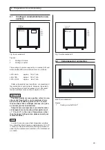
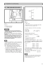
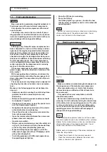
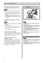
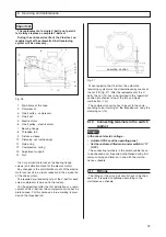
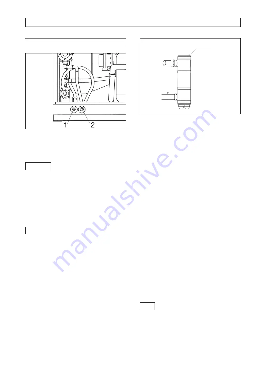
Fig. 11
Figure 11 :
1 Cooling water intake
2 Cooling water outlet
6. Preparations for commissioning
The cooling water circuit is completely assembled
and fitted in the screw compressor unit.
The water connections of L37S-L75 are as follows:
Permissible cooling water data :
• Cooling water pressure : >>min./max.<<:
L37S-L55
:
2 / 5 bar
L75
:
3 / 5 bar
• Cooling water inlet temperature :
>>min./max.<<: 5 / 35 °C
• Cooling water outlet temperature : >>max.<<: 55 °C
The cooling water requirement at maximum operating
pressure, related to a water inlet temperature of 12 to
15 °C,
∆
t = 15 °C :
L37S
approx.
40 l/min
L45
approx.
50 l/min
L55
approx.
60 l/min
L75
approx.
70 l/min
The cooling water quantity for the oil and air cooler
must be set by means of a manual control valve at the
time of commissioning.
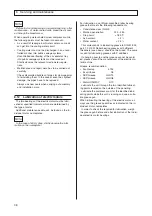
Compressed air outlet temperature
30 to 35 °C
Oil temperature
65 to 75 °C
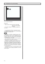
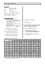
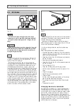
Fig. 12
Note
If possible, the cooling water outlet temperature
should be lower than 50 °C in order to avoid an
increased precipitation of lime.
Important
During danger of frost or extended periods of
standstill of the screw compressor unit, the cooling
water is to be drained.
Maintenance and repair work must be carried out
carefully.
Dismantled bundles of pipes have to be checked for
damage prior to being reinstalled. In the case of
even the slightest damage, the pipes have to be re-
placed. Always use new seals when carrying out
assembly and mounting work.
Note
Before first commissioning - or when re-commission-
ing after maintenance of the water-cooled units, the air
cooler must be bled via the bleed screw.
When operating water-cooled screw compressor sy-
stems, the following must be taken into account :
• As a result of leakage in oil/water coolers some oil
can get into the cooling water circuit.
• Cooling water must not be discharged in an uncon-
trolled manner to the public drainage systems. Un-
controlled overflowing of the oil separator reservoir
to the public drainage systems must be avoided.
Strictly observe the relevant waste water regulations.
L37S-L75W
• Water intake:
G 3/4 " / NPT 3/4"
• Water outlet:
G
1" / NPT
1"
1
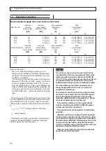
Figure 12 :
1 bleed screw


